Installation Guide National Electrical Code Compliance
6
TLS RF Wireless System Overview
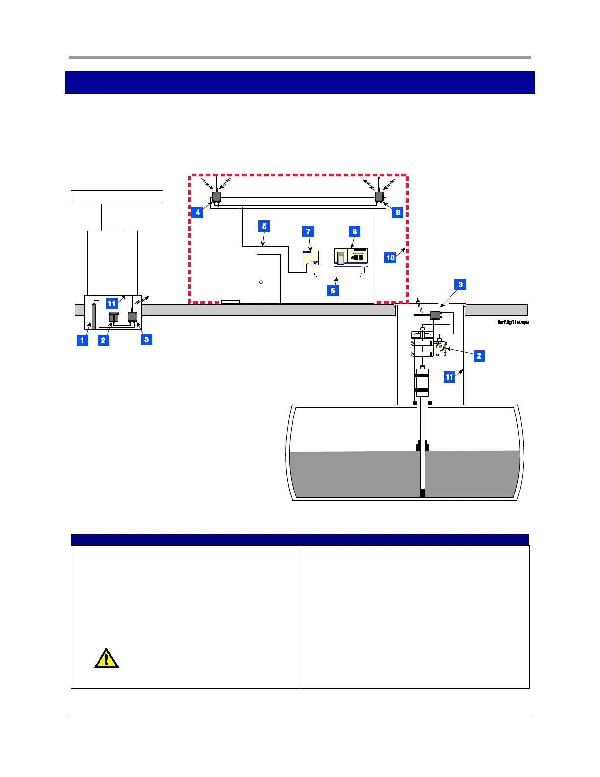
Figure 2 illustrates an example TLS RF Wireless System installation. In the figure only one tank is shown, but
each tank being monitored by a Mag probe would require a battery pack/transmitter pair. The repeater
component may be required if the system receiver, mounted on building’s outside wall, has difficulty receiving
signals from any of the transmitters.
Figure 2. Example TLS RF Wireless System component installation
LEGEND FOR NUMBERED BOXES IN FIGURE 2
1. Dispenser pan Mag Sump sensor
2. Battery Pack
3. Transmitter
4. Receiver
5. RS-485 cable (Belden #3107A or equiv.)
6. Probe wiring (up to 8 Mag probes/Mag Sump
sensors) - conduit connects via intrinsically safe
knockouts on both consoles.
NOTE: Intrinsically safe wiring shall be
installed in accordance with Article 504-20 of the
NEC, ANSI/NFPA 70.
7. TLS RF
8. TLS console
9. Repeater
10. Non-hazardous area
11. Hazardous area, Class I, Div. 1, Group D
 Loading...


