EasyManuals Logo

Veeder-Root TLS-350 PLUS Installation Manual

Veeder-Root TLS-350 PLUS
59 pages
To Next Page IconTo Next Page
To Previous Page IconTo Previous Page
Page #46 background imageLoading...
Page #46 background image
C-1
Appendix C: Device DIP Switch Settings
Use this appendix for DIP switch settings for all devices in the site.
TLS RF Device Number Settings
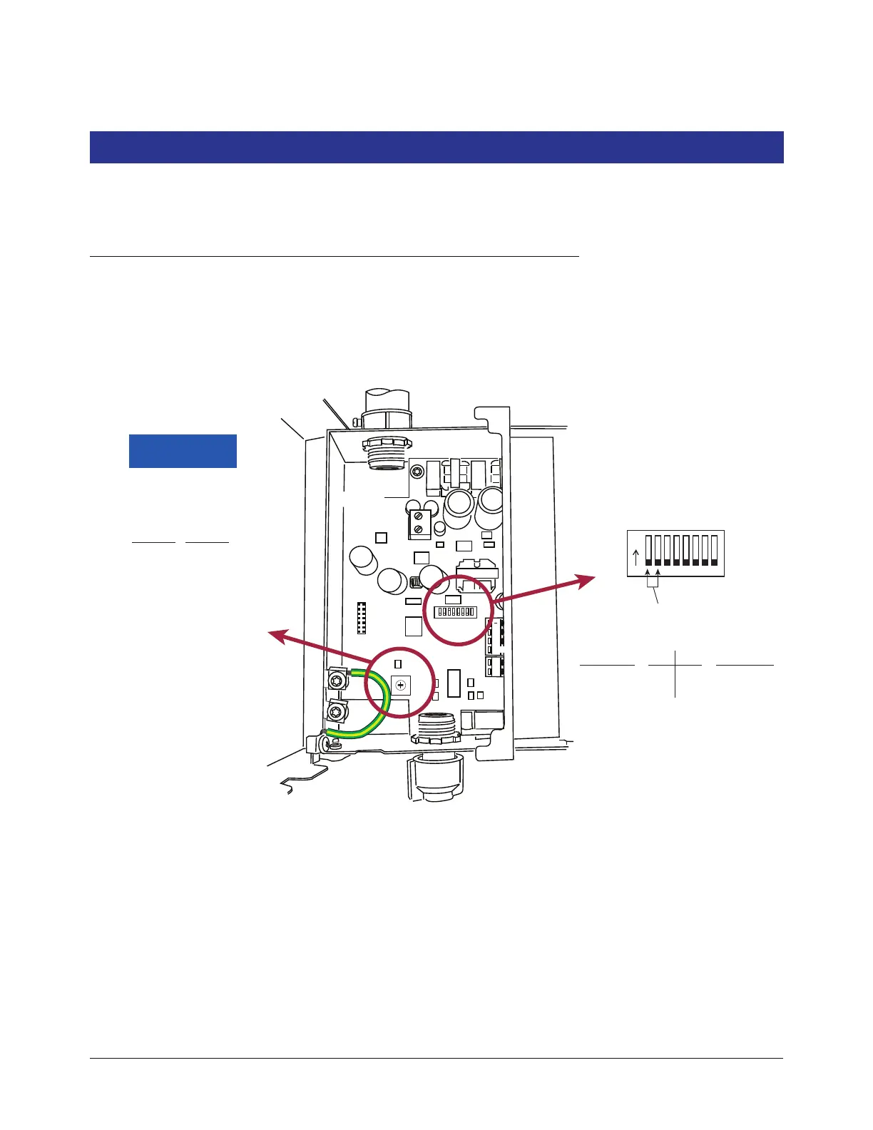
The Dip Switch Locations to set the unique Device number for the TLS RF unit are shown in the Figure C-1. The
TLS RF that monitors the Receiver and transmitter IDs 1 - 8 is considered the site’s master TLS RF unit and must
have its Device ID set to 0 (default).
Figure C-1. TLS-RF switch settings
A
B
C
D
E
F
0
1
2
3
4
5
6
+
G
15V
G
AC
INPUT
REPEATER
RS-485
15V
TLS RF
S2
ON
TLS RF Device ID
0 = Master
Device Timeout
(Time to Probe Out/Comm alarm)
Sw Pos
Delay
0
1
2
3
4
5
6
7
8
9
A
B
C
D
E
F
5 m
10 m
15 m
20 m
30 m
45 m
60 m
90 m
2 h
3 h
4 h
6 h
8 h
12 h
18 h
24 h
off off
off on
1 - 8
9 - 16
Sw1 Sw2
Transmitter
IDs
0 (default)
1
Device ID
c-1.eps

Other manuals for Veeder-Root TLS-350 PLUS

Questions and Answers:

Question and Answer IconNeed help?

Do you have a question about the Veeder-Root TLS-350 PLUS and is the answer not in the manual?

Veeder-Root TLS-350 PLUS Specifications

General IconGeneral
CategoryMeasuring Instruments
Number of Tanks SupportedUp to 16
Water DetectionYes
Inventory ManagementYes
Delivery ReportingYes
Alarm ManagementYes
DisplayLCD
EnclosureNEMA 4X
ModelTLS-350 PLUS
ManufacturerVeeder-Root
Temperature MeasurementYes
TypeAutomatic Tank Gauge
Leak DetectionYes
CommunicationRS-232, Ethernet
Product TypeTank Gauging System
ComplianceUL, ATEX

Related product manuals