Installation Guide Transmitter Installation
15
Wireless Component Installation
Transmitter Installation
MAG PROBE SUMP
A transmitter / battery pack pair must be installed in every tank’s probe/dispenser pan that will be monitored
by the TLS RF. Follow the steps below to install the transmitter assembly.
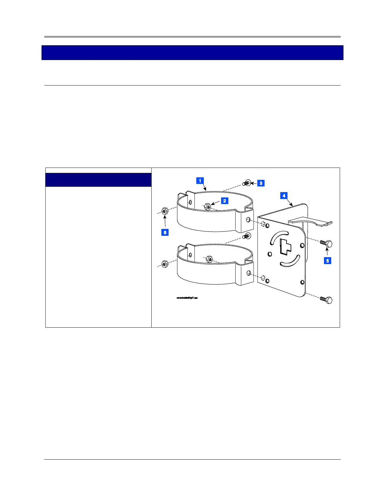
1. Connect the two conduit hangers from the kit (2- or 4-inch as required) to the battery pack support
bracket as shown in Figure 12.
2. Attach two conduit clamps to the battery pack support bracket as shown in Figure 13. Do not tighten
screws at this time.
LEGEND FOR NUMBERED BOXES IN
FIGURE 12
1. 2-inch or 4-inch conduit hanger [as
required] - 2 places
2. 1/4 x 20 hex head nut - 2 places
3. 1/4 x 20 x 1.25” hex head bolt - 2
places
4. Battery pack support bracket
5. 1/4 x 20 x 0.5” hex head bolt - 2
places
6. 1/4 x 20 hex head nut - 2 places.
Figure 12. Attaching hangers to battery pack support bracket
 Loading...


