Installation Guide Transmitter Installation
16
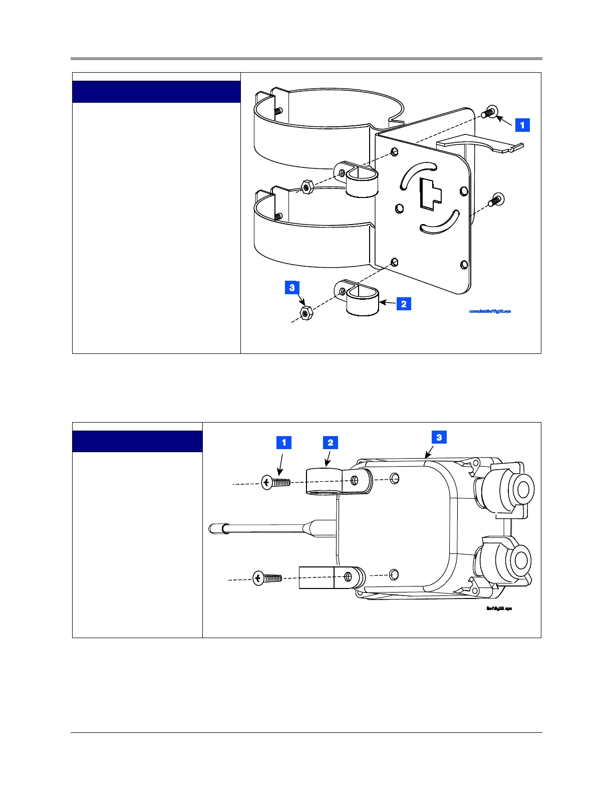
LEGEND FOR NUMBERED BOXES IN
FIGURE 13
1. #10 x 1/2’’ screw - 2 places
2. Clamp - 1/2” conduit - 2 places
3. #10 x 1/2’’ hex nut - 2 places.
Figure 13. Attaching conduit clamps to battery pack support bracket
3. Attach two conduit clamps to the transmitter as shown in Figure 14. Do not tighten screws at this time.
LEGEND FOR NUMBERED
BOXES IN FIGURE 14
1. #10 x 1/2’’ taptite screw -
2 places
2. Clamp - 1/2” conduit - 2
places
3. Transmitter housing
Figure 14. Attaching conduit clamps to transmitter housing
4. Loosen the probe cable cord grip and remove the riser cap. Thread the probe cable through the two
conduit hangers as you slide the hanger/bracket assembly onto the riser. Adjust the conduit hangers until
the top one is 3 - 4 inches below the top of the riser as shown in Figure 15. Tighten the two conduit
 Loading...


