Installation Guide Wiring the TLS RF
14
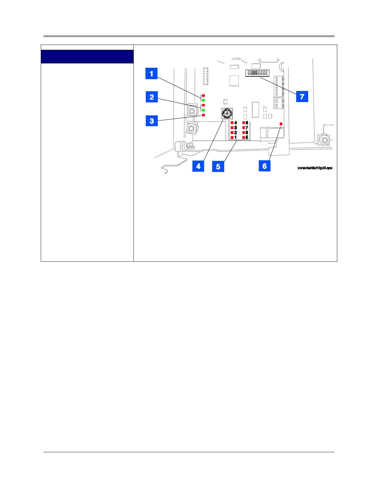
LEGEND FOR NUMBERED BOXES
IN FIGURE 11
1. These LEDs flash when there is
comm activity on RS-232 port
(Red = TX, Green = RX).
2. These LEDs flash when there is
comm activity on the RS-485
network (between TLS RF and
receiver).
3. Red LED is lit when TLS RF is
powered on.
4. Device timeout rotary switch
selects the maximum allowed
time to wait for communication
from transmitter before a
Probe Out/Comm alarm is
posted by TLS console (see
Appendix C for selections).
Position 1 (10 minutes) is the
factory default setting.
5. These red LEDs flash when a
message is received from a
transmitter in the monitored
device set. LED 1 is the device
wired to I.S. output terminal 1.
LED 2 is the device wired to
output terminal 2, etc.
6. Red LED flashes when TLS
console is polling for device
data.
7. S2 DIP switches 1 – 2 enter
device set address (see
Appendix C).
Figure 11. TLS RF diagnostic LEDs and switch locations
 Loading...


