ISD Post-Installation Checklist ISD with VST Balance system/VST EMC Membrane Processor CheckList
6
ISD with VST Balance system/VST EMC Membrane Processor CheckList
Procedure
The following recommended procedure can be followed at the completion of the ISD software setup for VST Balance Sys-
tems with VST EMC Membrane Processor:
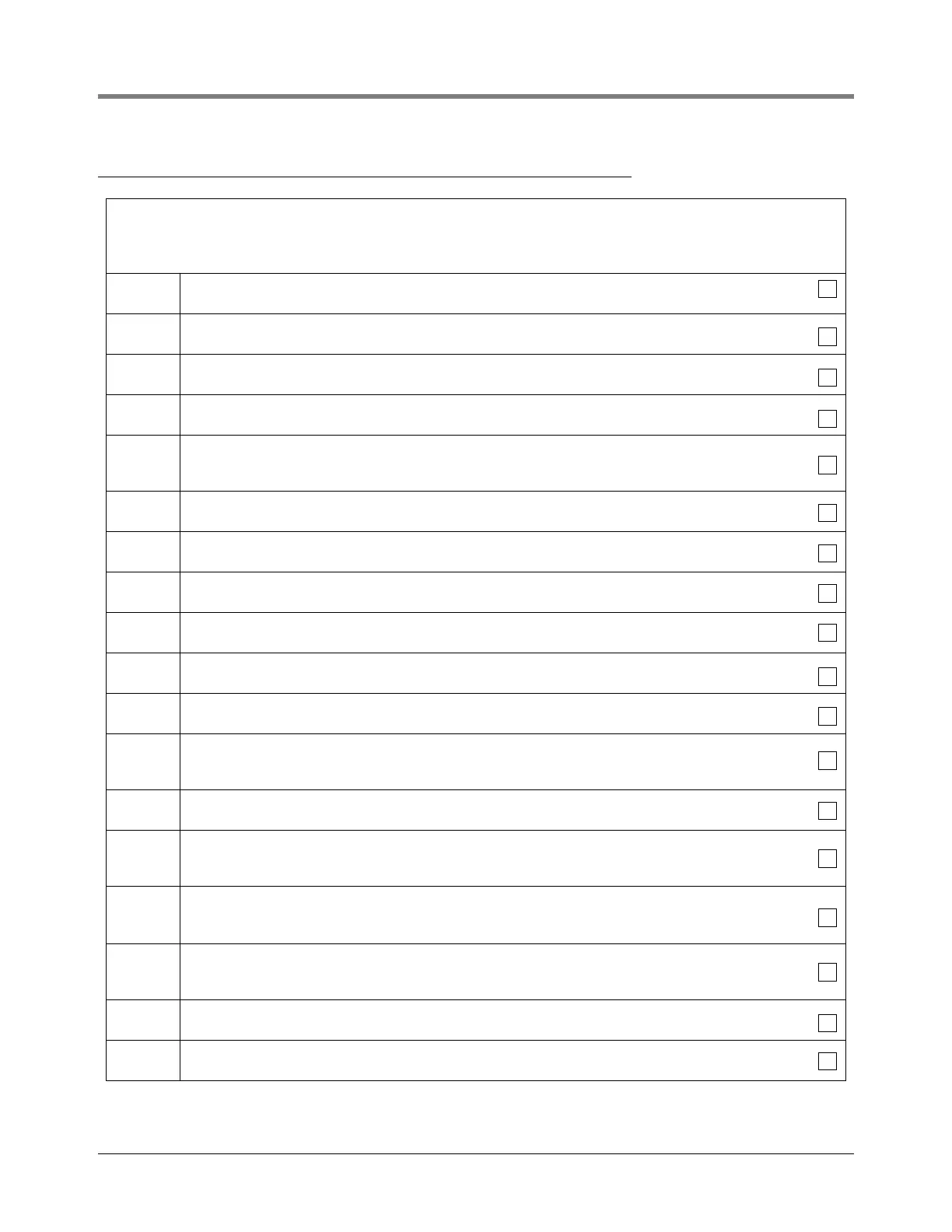
STEP 1. EVR TYPE is set to BALANCE?
STEP 2. The Balance Nozzle Type is VST?
STEP 3. The Vapor Processor set to VST Vapor Processor?
STEP 4. There is a wired and ENABLED Hydrocarbon Sensor?
STEP 5.
There is a wired and ENABLED ‘AIRFLOW METER’ (i.e. ISD Vapor Flow Meter) in each vapor recovery
dispenser?
STEP 6. There is a wired and ENABLED ‘PRESSURE SENSOR’ (i.e. ISD Vapor Pressure Sensor)?
STEP 7. The FUEL HOSE TABLE is setup and filled out for each vapor recovery hose?
STEP 8. The ISD FUEL GRADE HOSE MAP does not contain entries for non vapor recovery hoses (e.g. diesel)?
STEP 9. PMC setup Vapor Processor Max Runtime is set to 30 minutes?
STEP 10. PMC setup Turn Off Vapor Processor is set to -0.2 IWC?
STEP 11. PMC setup Turn On Vapor Processor is set to +0.2 IWC?
STEP 12.
On the TLS press MODE key until the SETUP MODE menu is displayed, enter setup then
exit SETUP MODE (this will cause the TLS console System Self Test).
STEP 13. Using the Troubleshooting Guide respond to all ISD Setup ALARMS posted on the printer tape.
STEP 14.
Repeat Steps 12 & 13 until there are no ISD setup or self-test alarms. The TLS Console display reads
ALL FUNCTIONS NORMAL.
STEP 15.
Using the ISD PC Setup Tool and the ISD Vapor Pressure Sensor calibration valve: The ISD Vapor
Pressure Sensor reads an ambient pressure reading with an offset no greater then
± 0.20 IWC?
STEP 16.
Returned the ISD Vapor Pressure Sensor calibration valve so that the sensor is reading
UST vapor pressure?
STEP 17. Using the ISD PC Setup Tool: An ISD A/L reading is coming in for each gas hose at the location?
STEP 18. The TLS console clock is set to the correct date & time?
 Loading...


