OTDR Series e-Manual, D07-00-076P-RevC00 Page 86 of 107
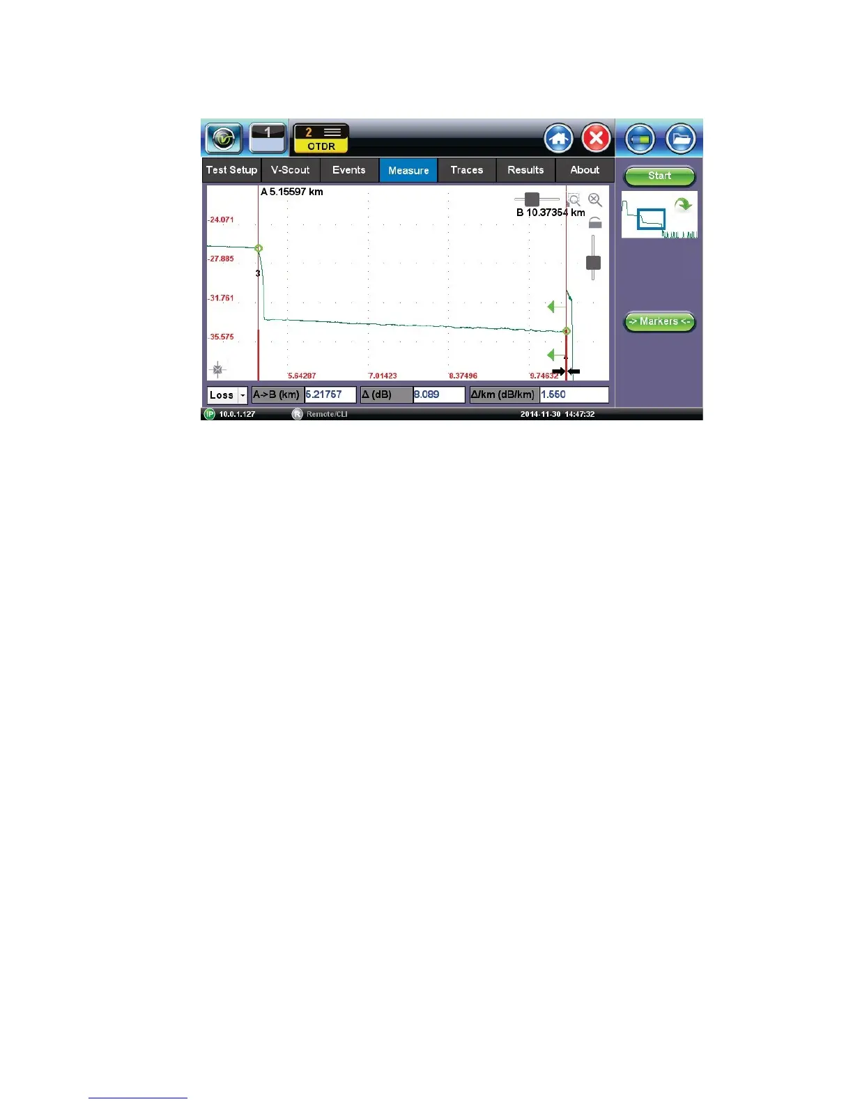
7.5.2 Distance Measurements
D
i
s
t
a
n
c
e
m
e
a
s
u
r
e
m
e
n
t
–
m
e
a
s
u
r
e
e
x
p
a
n
d
e
d
t
r
a
c
e
v
i
e
w
m
o
d
e
When a trace is displayed as show above, the fiber length is automatically measured from the
start of the trace (or Span Begin) to each of the two markers and in between the markers.
Proper marker placement is critical for accurate measurements. To position the marker/s
accurately, expand the trace horizontally and vertically (using the Zoom Controls) and position
the marker on event’s left edge (first rising or falling pixel).
The distance (km, miles or feet) will be indicated next to the top of the marker.
Note: The distance accuracy depends on the correctness of optical fiber refraction index value
setting.
7.5.3 Loss Measurements
Loss Modes - Several Loss modes are available for manual measurements depending on
measurement application:
• 2-Pt Loss
• 2-Pt LSA
Two Point Loss measurement
• Reflectance
• ORL (Optical Return Loss)
• Splice Loss
7.5.3.1 Two Point Loss (2-Pt Loss)
The 2-Point Loss mode uses a data point at Marker A and Marker B to calculate the dB level
difference between the two points. Usually the backscatter level value of Marker A is greater
than the level of Marker B and a positive loss measurement is displayed. If the loss value is
reported as a negative quantity, it is termed a “gainer.” Measure loss between two points using
the Loss (2-point) mode (using two markers):