13
4 Mounting
VEGAMET 841 • 4 … 20 mA
58864-EN-200312
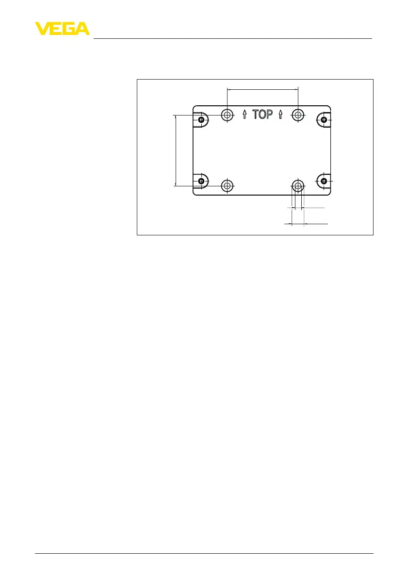
Loosen the four screws in the housing cover and open it to the left.
Fasten the device to the mounting plate using the screws (M5) sup-
plied.
82 mm
(3.23")
ø13 mm
(0.51")
ø7 mm
(0.28")
82 mm
(3.23")
Fig. 3: Mounting plate for wall mounting VEGAMET 841
Zur Rohrmontage ist das optional bestellbare Montagezubehör
erforderlich. Dies besteht aus zwei Paar Montageklammern und vier
Montageschrauben M6 x 100.
Die Montageklammern werden gemäß nachfolgender Abbildung an
der Montageplatte und dem Rohr angeschraubt.
Lösen Sie die vier Schrauben im Gehäusedeckel und klappen
diesen nach links auf. Befestigen Sie das Gerät mit den beiliegenden
Schrauben (M5) auf der Montageplatte.
Rohrmontage

 Loading...