17
5 Connecting to power supply
VEGAMET 841 • 4 … 20 mA
58864-EN-200312
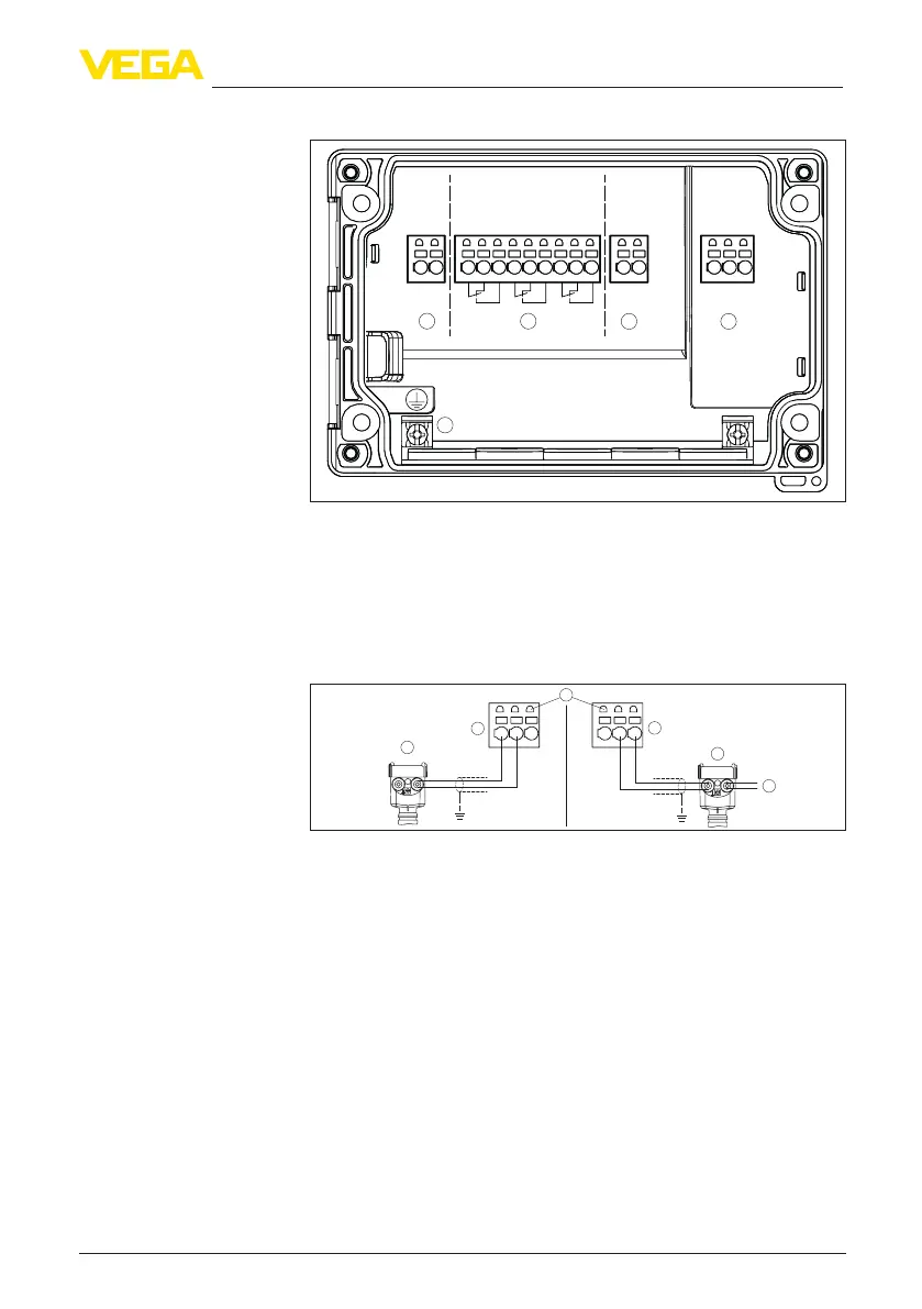
5.4 Wiring plan
91 92
LN
+- +-
61 62 63 64 65 66 67 68 69
41 42
123
Power 32
ensor
Relay Output
Output
Current
1 2
3
4
5
Fig. 6: Wiring plan VEGAMET 841
1 Voltage supply of the controller
2 Relay outputs 1 … 3
3 Current output
4 Sensor input (active/passive)
5 Ground terminal for protective conductor
Detail Sensoranschluss 1
+-+-
1 23 1 23
3
1
5
4
2
Fig. 7: Anschluss Eingang 1 für Zweileiter-/Vierleitersensor (aktiv/passiv)
1 Aktiver Eingang mit Sensorversorgung für Zweileitersensor
2 Passiver Eingang ohne Sensorversorgung für Vierleitersensor
2)
3 Zweileitersensor
4 Vierleitersensor
5 Spannungsversorgung für Vierleitersensor
6 2 mm-Buchsen zum Anschluss eines VEGACONNECT/HART-Handheld
5.5 Einschaltphase
Nach dem Einschalten führt das Gerät zunächst einen kurzen Selbst-
test durch.
•
Interne Prüfung der Elektronik
•
Ausgangssignale werden auf Störung gesetzt, Hintergrund-
beleuchtung des Displays leuchtet rot
2)
Passiver Eingang bei Ex-Ausführung nicht verfügbar

 Loading...