SI23 Solar Pump VFD Manual
14
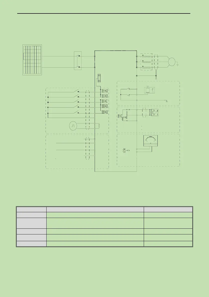
2.2 Solar Pump Controller Wiring
● Standard Connection Diagram
Analog Monitoring Signal Output
TA
TB
TC
+24V
Y
_
mA
20
10
0
-
+
V
W
U
M
~
E
(The grounding resistance is
less than10Ω)
W
V
U
Output Reactor
+10V
Analog Input
GND
AI1
AI2
Multiple Functional Contact Input
(REV)
(FWD)
X1
X2
VFD
PV-
PV+
GND
AO1
Coil
COM
Passive Contact
Output
Coil
MAX Output:
5A/30VDC
1 +24V Max. Output:DC24V/100mA
2 Y Max. Output:DC24V/50mA
Note:
+24V
GND
Analog Voltage/Current Input 1
A+
B-
RS485 Communication
120Ω
Analog Voltage/Current Input 2
Open Collector
State Ouput
1 +10V Max.Output:50mA
Note:
PV modules
DC breaker
(Water full detection alarm)
COM
X3
(Water full detection reset)
X4
(Free stop)
X5
Note: 1.When connect solar panel, please connect PV+/PV-.
2.The communication interface of the PCE is considered as DVC A. The external signal communication interface is
considered as SELV. The compatibility shall be considered when the communication interfaces are connected.
● Auxiliary Terminal Output Capacity
10V auxiliary power supply output, constitutes loop with GND.
Analog monitor output, constitutes loop with GND.
Max output 2mA as frequency,
voltage signal
24V auxiliary power supply output, constitutes loop with COM.
Collector open circuit output; can set the action-object by program.
Passive connector output; can set the action-object by program.
 Loading...