IG-032-EN version 05; 18/06/2019
26
Installation
General instructions
pfu basic range: Prefabricated concrete
enclosure, ground-level walk-in type
8.5. Earth connection
The pfu is tted with two internal earthing circuits. These
earthing circuits connect to the exterior earthing networks.
The installer or nal user must provide suitable safety
measures in order to avoid dangerous touch and step
voltage.
The installation project must include the section for
implementation of the earthing installation, along
with justi cation of sizing in accordance with local
legislation.
8.5.1. Protective earthing circuit.
The protective earthing circuit (metallic part) includes
earthing of the metallic elements which may be under
voltage in the event of fault, and the reinforcement of the
prefabricated concrete building.
The protective earthing circuit nishes in a switch box. The
exterior protection earthing circuit connects to this switch
box.
The wire reinforcement of the body and the enclosure
roof are connected directly to the disconnection box.
Both reinforcements are electrically joined by an interior
connector.
Before putting the electrical installation into service,
make sure that the earthing connector between the
body and the roof of the pfu is connected.
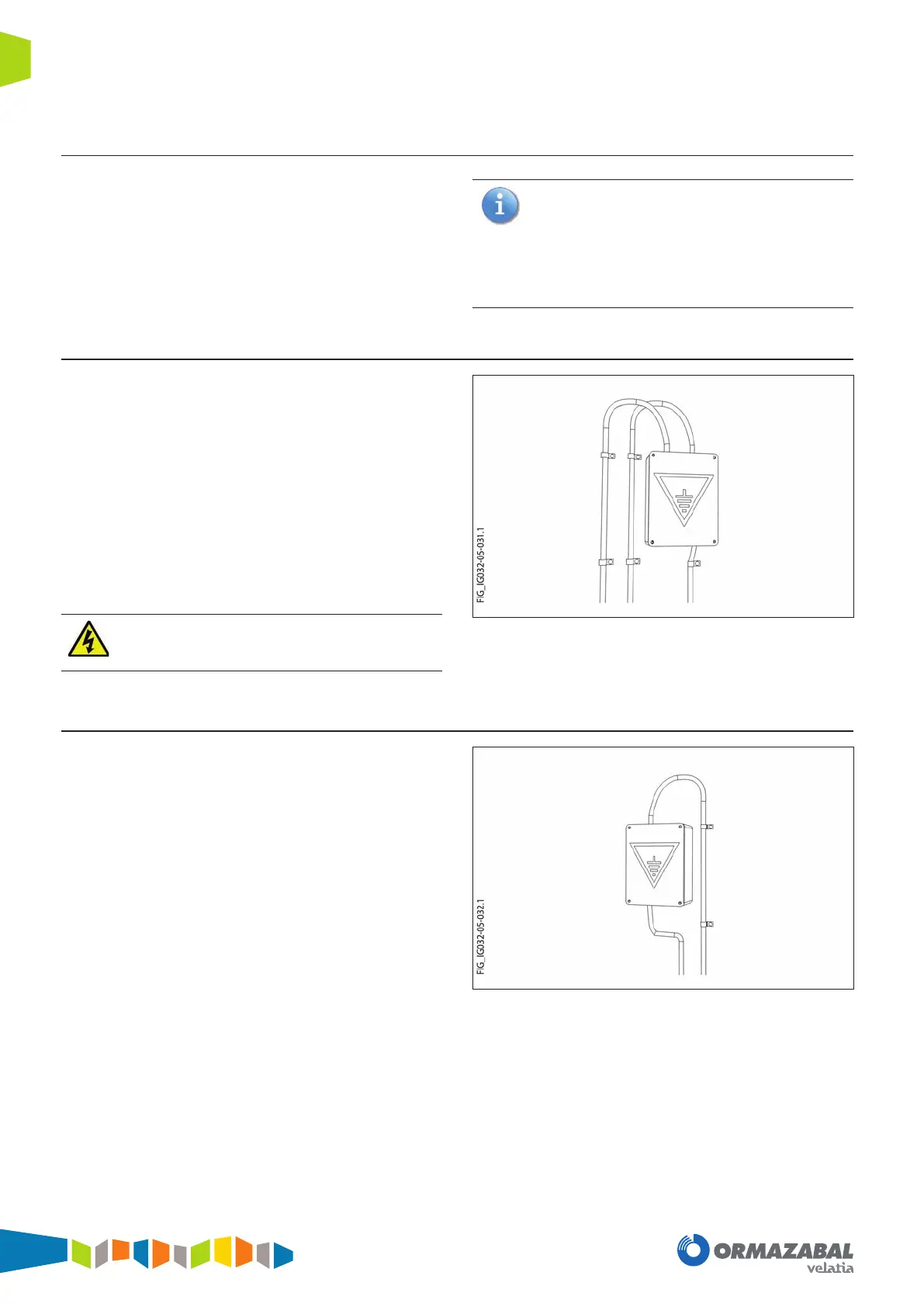
Figure 8.8. Example of protective earthing circuit switch box
8.5.2. Operational earthing circuit
The operational earthing circuit (neutral) joins the
transformer's neutral to the operational earthing switch
box. The exterior operational earthing circuit connects to
this switch box. Whenever two distribution transformers
are housed, two operational earthing circuits will be tted,
along with their associated switch boxes.
Figure 8.9. Example of operational earthing circuit switch box