Home
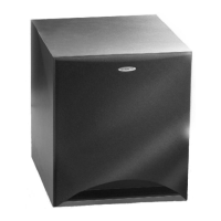
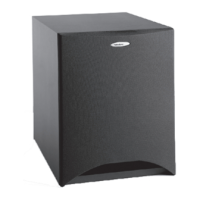
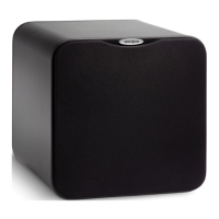
Velodyne
Subwoofer
EQ-Max Series
Velodyne EQ-Max Series User Manual
4
of 1
of 1 rating
28 pages
Give review
Manual
Specs
To Next Page
To Next Page
To Previous Page
To Previous Page
Loading...
WWW
.VELODYNE.COM
EQ-Max Series User
’s Manual - 5
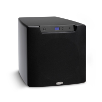
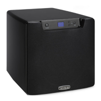
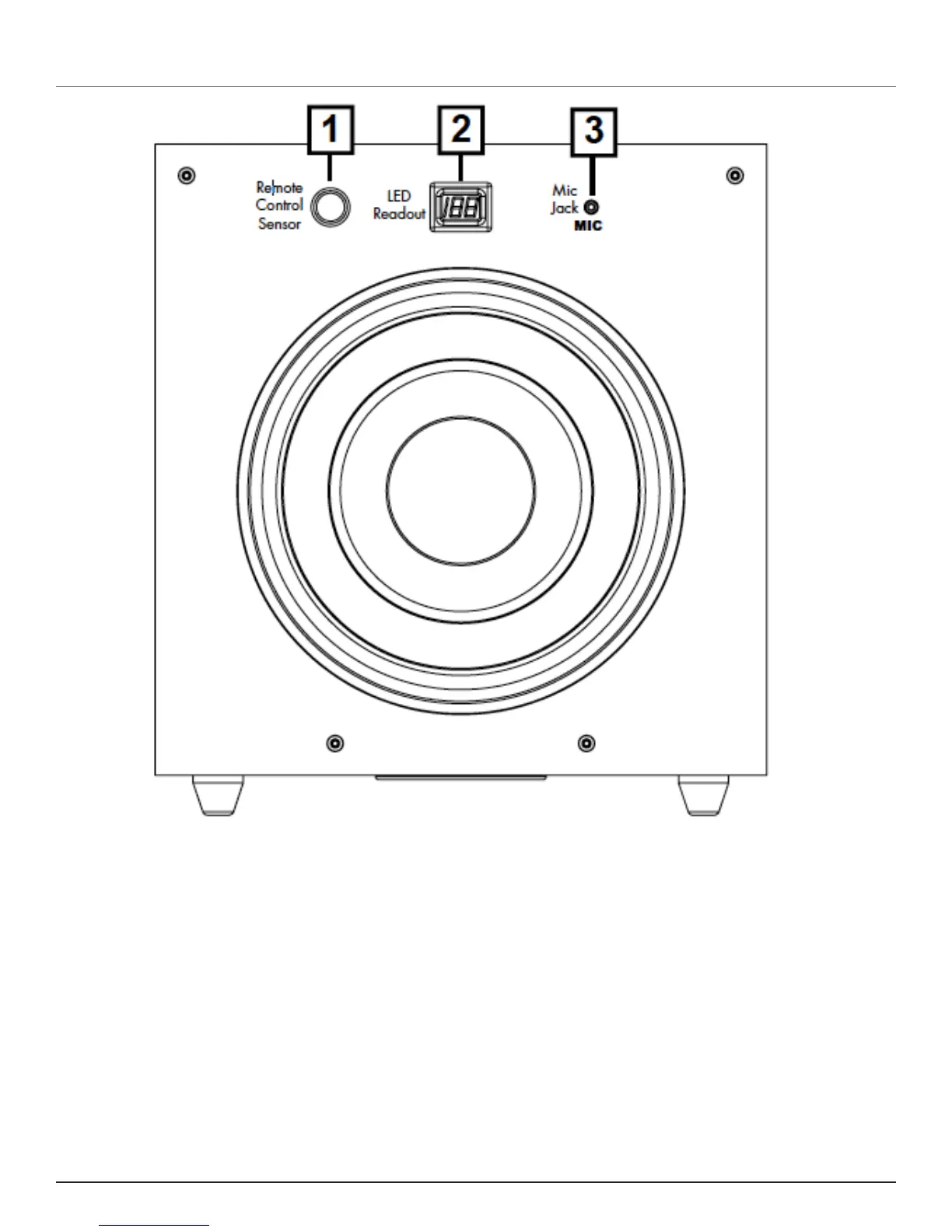
FRONT P
ANEL
Figure 1. EQ-MAX Fr
ont Panel
Following are brief descriptions of the contr
ols and connections described in Figur
e 1.
(1)
REMOTE CONTROL SENSOR
IR sensor window receives a signal fr
om the included r
emote contr
ol.
(2)
LED READOUT
2.5 digit, eight segment LED readout displays volume, phase and Auto-EQ.
(3
)
MIC JACK
Connector for the supplied microphone to use during the Auto-EQ pr
ocess.
10
12
Table of Contents
Table of Contents
5
Congratulations
7
Installation
8
Front Panel
11
Rear Panel Connections
12
Crossovers
15
Interconnect Cables
18
Usage
18
Maintain
21
Restoring Defaults
21
Clean
21
Service
21
Troubleshoot
22
Packaging
22
Listen Responsibly
23
Trademarks
23
Specifications
24
Warranty
24
Other manuals for Velodyne EQ-Max Series
Specifications
1 page
4
Based on 1 rating
Ask a question
Give review
Questions and Answers:
Need help?
Do you have a question about the Velodyne EQ-Max Series and is the answer not in the manual?
Ask a question
Velodyne EQ-Max Series Specifications
General
Enclosure Type
Bass Reflex
Auto On/Off
Yes
Driver Size
12 inch
Inputs
Line-Level
Outputs
Line-Level
Phase
0 or 180 degrees
Related product manuals
Velodyne 1000
22 pages
Velodyne CHT-15
12 pages
Velodyne CHT-10
12 pages
Velodyne MiniVee
20 pages
Velodyne CHT-10R
18 pages
Velodyne SUBWOOFER
19 pages
Velodyne DLS-3500R
9 pages
Velodyne SPL-ULTRA
2 pages
Velodyne VRP Series
17 pages
Velodyne Digital Drive
57 pages
Velodyne SPL-1200 Ultra
1 page
Velodyne DIGITAL DRIVE SERIES
57 pages
 Loading...