Inspection of solar storage tank – Part 3: Solar water heater system installation – 21
Inspection of solar storage tank
Prior to installation, inspect the solar storage tank for possible damage. Check markings on the rating plate to be certain the
power supply corresponds to that for which the water heater is equipped (electric back-up tank only).
Solar storage tank and pump station controller installation
The design and installation of the VELUX solar water heating system should be done by qualifi ed individuals that have been
trained in the proper installation techniques for VELUX solar water heating systems. It is important that good design and
installation practice be followed to assure that your system will operate properly. Failure to follow installation guidelines for
your VELUX solar water heating system could cause component failure and possible safety issues.
It is mandatory that all plumbing be done in accordance with all local and state codes or warranty will be void. It Is also
necessary on all solar loop piping mechanical connections to use both thread tape and the gaskets provided. The solar loop
piping heat exchanger connections are located on the side of your solar storage tank, and also on the top and bottom of the
pump station controller.
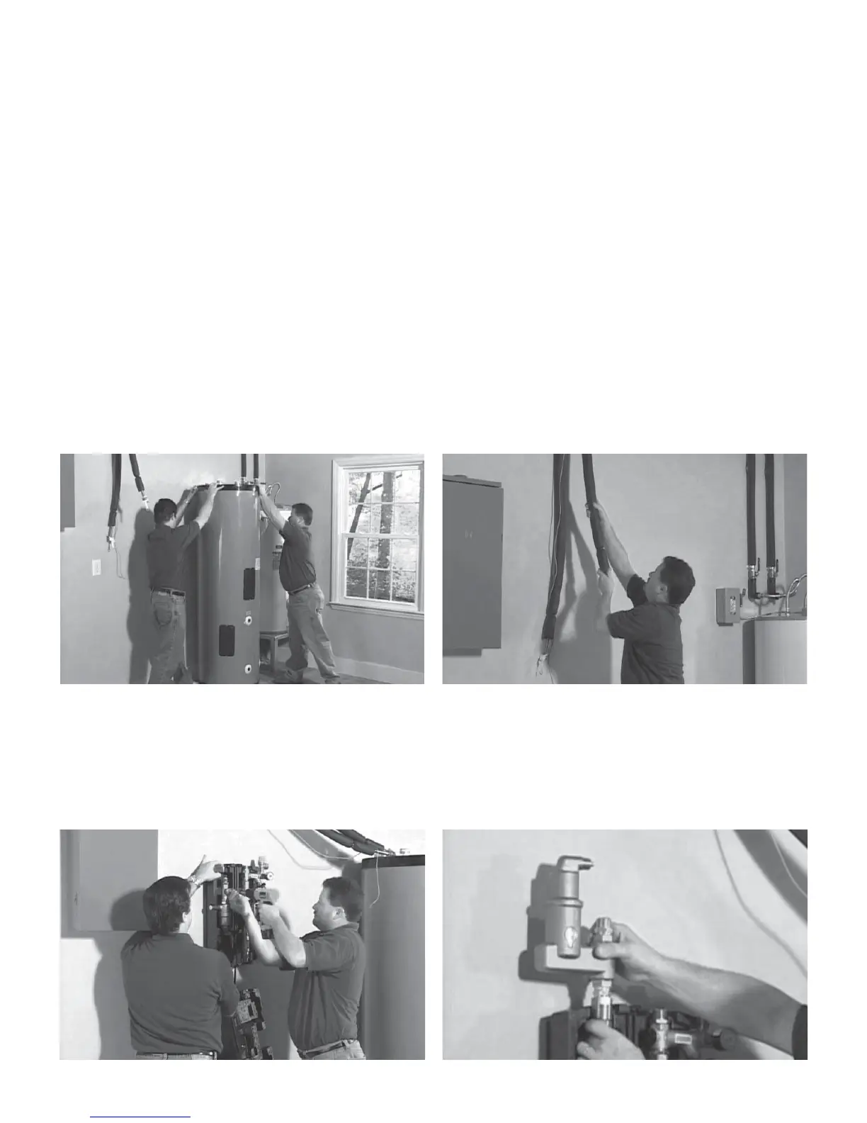
1. Carefully place storage tank in predetermined location and route the collector hot supply and cold return fl exible
pipes and collector sensor wire to the wall adjacent to the storage tank (area pump station controller will be
installed).
2. Attach the pump station controller to the wall adjacent to the tank. The pump station controller should be installed
within 4’ of solar tank heat exchanger connections. Install the microbubble air separator to collector “hot” line
connection on the top left corner of the pump station controller.
 Loading...