Programming system controller – Part 3: Solar water heater system installation – 29
!
CAUTION
The pressure in the glycol loop should not exceed 80 PSI when the system is in operation on a sunny day. Contact your Solar
Contrator if your collector loop exceeds this threshold.
Programming system controller
After the glycol loop has been charged the controller must be set to the desired settings. The solar control comes programmed
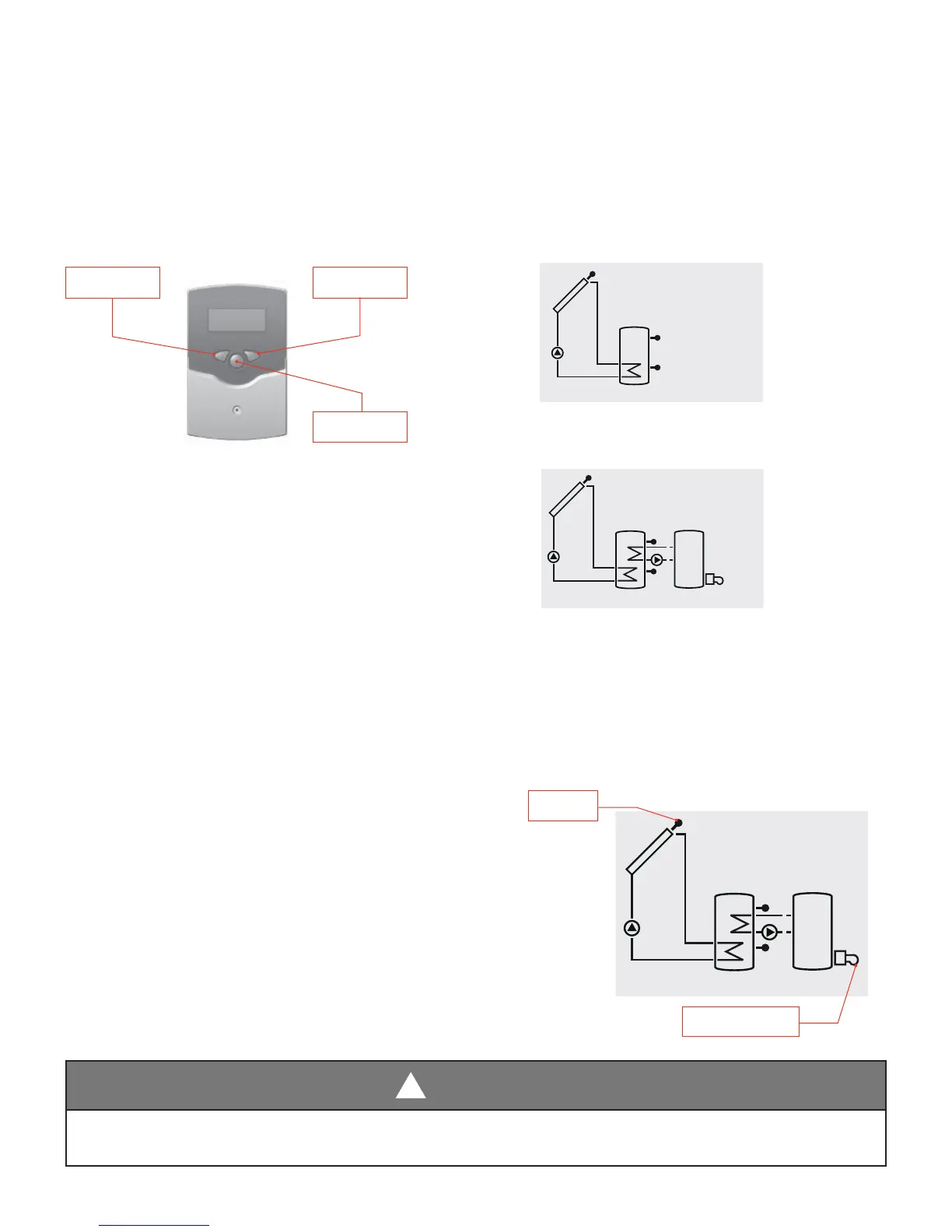
with default settings for backup electric or solar preheat systems. The controller is operated by three push buttons located
below the display. The forward-key (1) is used for scrolling forward through the menu or to increase the adjustment values.
The backwards-key (2) is used for scrolling backward through the menu or to decrease the adjustment values.
1. To enter the programming mode, repeatedly press the forward button (1) until “hP” is displayed. With “hP” displayed
depress and hold the forward button (1) for 2-3 seconds to enter program mode. Scroll forward until “Arr” (system
arrangement) is displayed -- the default is “Arr 1” as shown.
(Electric backup and pre-heat systems)
2. Change to boiler backup (boiler back-up systems only).
Depress the Set button (3) so that “Set” is displayed. Scroll
forward until “Arr 2” is shown. Depress the Set button (3)
so that program change is saved and “Set” is removed from
the display. System is now ready to operate in boiler back-up
confi guration.
3. Depress the forward button (1) repeatedly until “OCX”
shows on display. Depress the Set button (3) so that “Set” is
displayed. Scroll forward until “On” is shown. Depress the Set
button (3) so that program change is saved.
4. Depress the forward button (1) repeatedly until “OREC” shows on display. Depress the Set button (3) so that “Set” is
displayed. Scroll forward until “On” is shown. Depress the Set button (3) so that program change is saved.
System controller operation
During normal operation the controller will function as follows:
1. Controller LED
− Constantly green: everything functioning properly
− Red/green blinking: system initialization phase manual operation
− Red blinking: sensor defect (sensor symbol is quickly blinking)
2. Controller system screen
− Pumps are blinking during starting phase
− Sensors are quickly blinking in case of sensor defect
− Burner symbol is blinking if after-heating is activated
Arr 1
Arr 2
Sensors
Boiler backup
2: Backward
3: Set
1: Forward
 Loading...