HP25E / HP30E 4. Setting up
4-3© VEMAG 2018
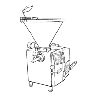
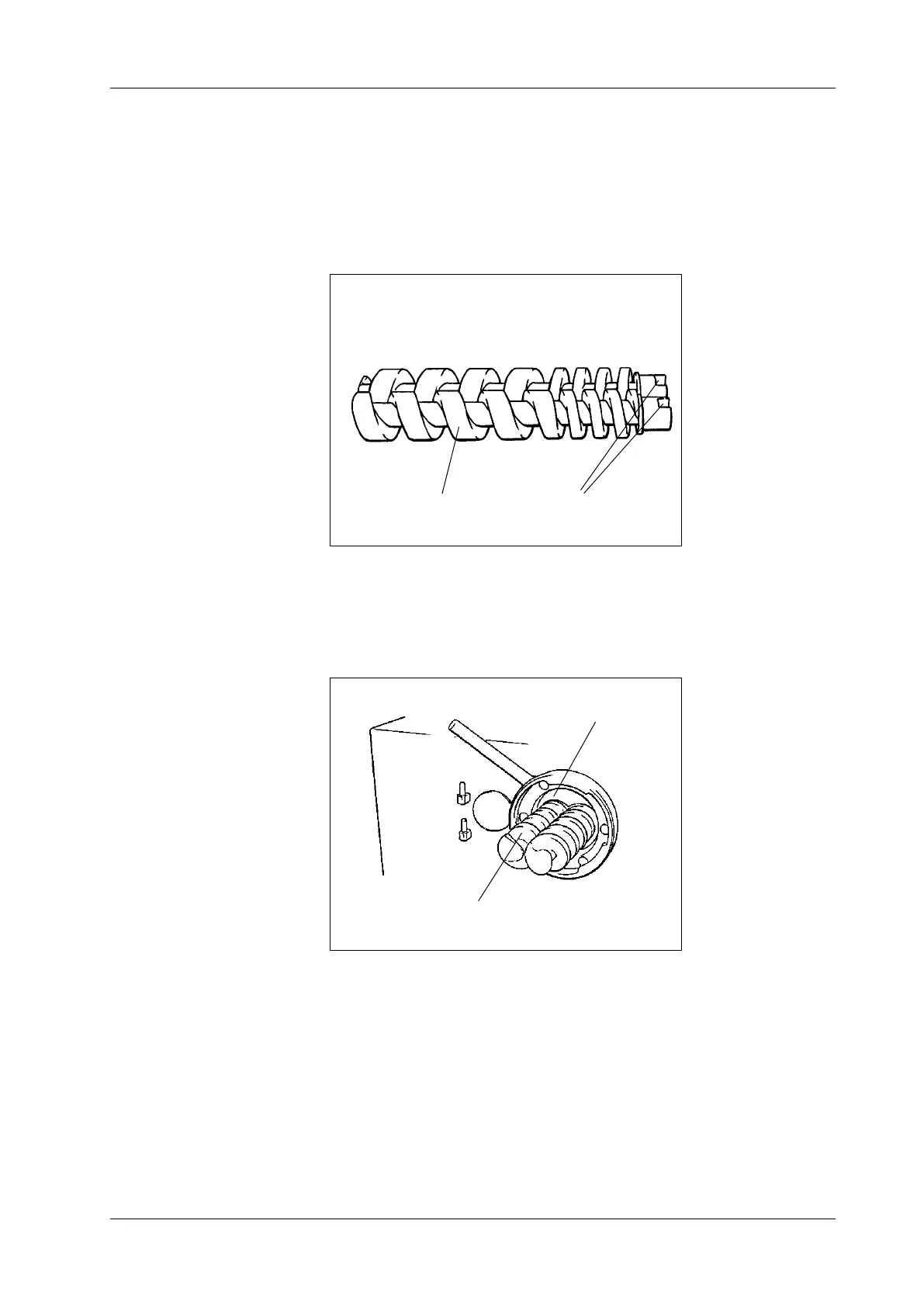
4.3 Fitting the double screws
• Position the double screws (1) so that the screw marked left (”links”) is
on the left-hand side and the front faces are ush.
• Bring the slots of coupling claws (2) into the correct position in relation
to the coupling pins in the feed cylinder by turning the double screws
in opposite directions.
1 Double screws
2 Slots
Fig. 4-3
Lining up the double
screws
1
2
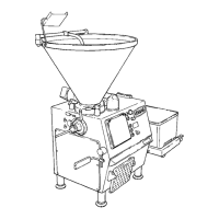
• Push double screws (1) into double screw housing (2) up to the stop.
The double screws are properly engaged if the end faces of the dou-
ble screws and housing are ush.
1 Double screws
2 Double screw housing
Fig. 4-4
Installation of double
screws
1
2
 Loading...