3/2002
PC-19
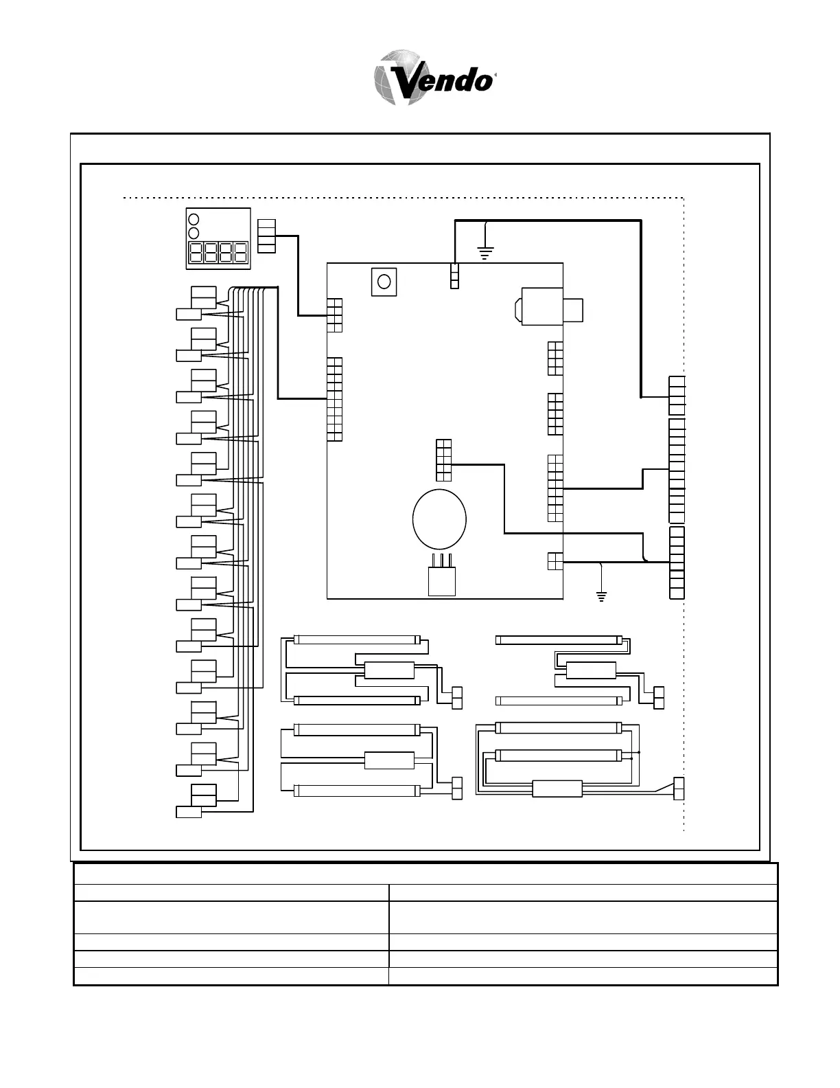
9.1 WIRING DIAGRAM
VOLTAGE READINGS
J1 - Temp Sensor 5 Volts DC Pins 1 and at 2 J8 - MDB Port 34 Volts DC at Pin 1 5 Volts DC at Pin 6
J3 - DEX Port only 0 Volts DC J10 - Vend Motor Port 15 Volts DC Pins 1 and 12, 24 Volts at
Pins 8 and 16, and 13 Volts at Pin 3, 4 and 10
J4 - Display Port 5 Volts DC at Pins 6 and at 3 J11 - Environmental Control Port 24 Volts DC Pins 1,2 and 3
J5 - Option Port 5 Volts DC Pin 1, 2, 3, 4, 7 J13 - Main Power Input 24 Volts AC Pin 3
J6 - Selection Port 5 Volts DC Pins 3, 4, 5, 13, 14 All Power readings were off the J13 Pin 2 ground
PHILLIPS ELECTRONIC
LAMP
LAMP
LAMP
LAMP
SLIM LIN
SEL. # 13
VIO
WHT
WHEN USED
BLU
PNK
WHT
20
1
19
18
1
9
8
GR
VI
YEL
16
15
14
13
ORN
BRN
6
5
4
3
11
12
2
1
J6
ORN
RED
BLK
84
3
VI
15
62
J4
BRN
WHT
SEL. # 12
BRN
WHT
YEL
SEL. # 10
SEL. # 11
GRY
BLU
SEL. # 9
ORN
BLU
VIO
SELECTION SWITCHE
SEL. # 8
SEL. # 7
BLU
BRN
BLU
SEL. # 6
YEL
BLU
GRY
SEL. # 5
SEL. # 4
PNK
ORN
PNK
SEL. # 3
PNK
VIO
ORN
SEL. # 1
SEL. # 2
COM
PNK
YEL
NO PNK
4
BLK
RED
DISPLA
1
VI
WHEN USED
WHEN USED
WHEN USED
WHEN USED
WHEN USED
BALLAST
HIGH OUTPUT
2
1
2
1
OSRAM ELECTRONIC
BALLAST
LAMP
DOO
2
1
BALLAST
LAMP
BALLAST
1
2
LAMP
LAMP
GRN
GRN
WHT
3
4
1
2
BLK
J13
GRY
VIO
YEL
10 5
8
9
7
ORN
4
3
2
J11
6
BRN
1
J8
SOCKE
MDB
YEL9
J10
1
PNK
GR
VIO10
11
12
13
2
3
4
5
RED
WH
14
15
16
6
8
BLK
BLU
BRN
ORN
WH
J7
9
8
4
3
2
10 5
16
MODE
SWITCH
15
2
3
4
6
8
SOCKE
DEX
J3
J5
1
2
J1
3BLK
WH
RED
VEC 9.1 OR 9.
CONTROL BOARD
BRN
ORN
GRY
WHT
BLK
8
VIO
ORN
BLU
BLK
WHT
12
1
YEL
GRY
RED
WHT
BRN
PNK
1
VIO
YEL
RED
WHT
SHLD
BLK
4
1
GRN
DOO
 Loading...