SECTION D
SERVICE & MAINTENANCE
D-6 VENTRAC 3000 VPI
DRIVE BELTS
The VENTRAC 3000 has three drive belts: one
PRIMARY drive belt, one REAR transaxle belt and one
FRONT transaxle belt.
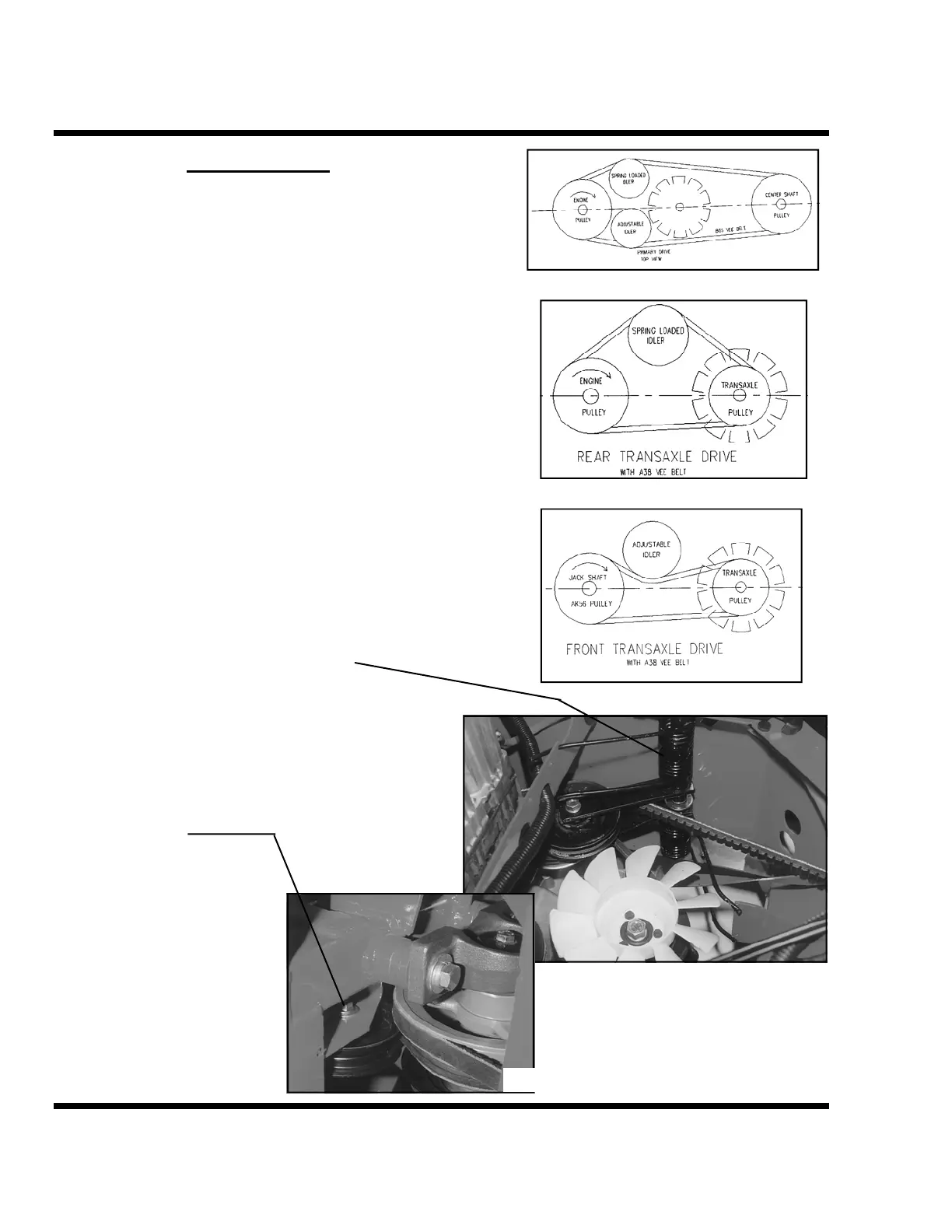
The PRIMARY DRIVE BELT (Figure LTB-A) connects
the engine pulley to the center drive shaft pulley in the
pivot area of the articulated frame. It is the top belt in the
drive system. It has two vee belt idlers. One fixed idler
just below the right front corner of the engine and other
spring-loaded idler on the opposite side.
The REAR TRANSAXLE BELT (Figure LTB-B) is the
lower belt. It connects the lower engine pulley to the rear
transaxle pulley with the plastic-cooling fan. It has one
vee belt idler located just below the primary drive belt
spring loaded idler.
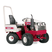
The spring-loaded idlers have a unique torsion spring
tension system. The spring is mounted on the axis of the
leverage and has two extended prongs. The prongs can be
engaged individually making the tensioning process
manageable by hand. This leverage for the two rear drive
belts is located on the same axis (Figure 11).
The FRONT TRANSAXLE BELT (Figure LTB-C) is
located on the front chassis frame. It is on the same plain
as the rear transaxle belt. It goes from the center drive
shaft pulley to the front transaxle pulley with the plastic-
cooling fan. This belt has a fixed flat belt idler located
just below the crossover frame in the center pivot area of
the chassis. Figure 12).
All idlers should maintain proper alignment with the
belts. Mounting points should always position the idlers
in the same horizontal plain as the drive and driven
pulleys. Any angular positioning
will compromise the life of the
belt. Due to the vibration nature
of spring loaded idlers the bolts
securing them should be check
periodically to assure tightness.
Figure LTB-A
Figure LTB-B
Figure LTB-C
Figure 11
Figure 12