SERVICE
Service - 52
booster battery’s negative (-) terminal (3).
8. Connect the other end of the negative (-) booster
cable to the disabled power unit’s ground stud (4).
9. Start the disabled power unit and remove the
booster cables in reverse order of installation
(negative booster cable rst).
TCM (Tractor Control Module) Explanation
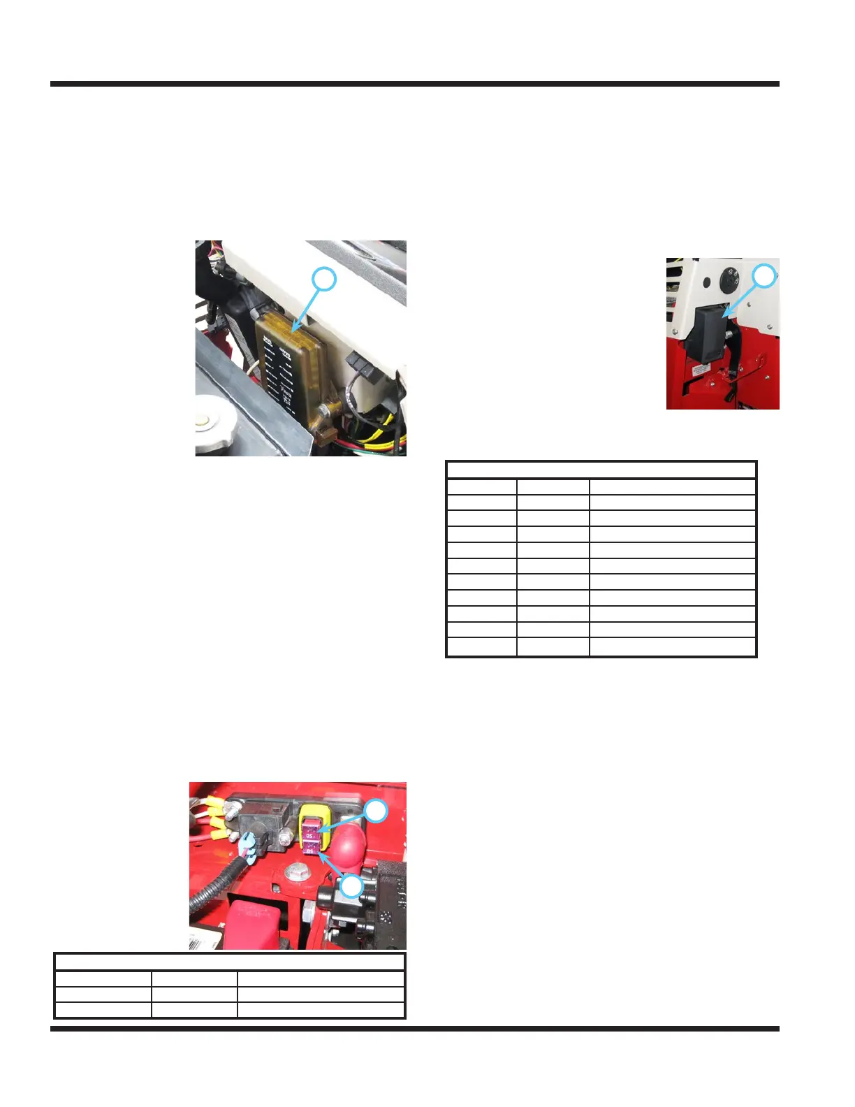
The Tractor Control
A
Module (A) is a
sealed computerized
device designed to
control the electronic
safety related
functions of this
tractor. Both solid
state and mechani-
cal components are
used to assure safe,
reliable operation of
this machine.
This TCM monitors the electronic circuits necessary
for the engine, starter, and PTO to function. These
“input” circuits include the PTO Switch, Neutral Switch,
Parking Brake Switch, Key Switch, Seat Switch, and
Generator Presence. The TCM is programmed to
allow the engine, starter, or PTO to operate only when
specic input criteria are satised. The engine, start,
and PTO are controlled by “outputs” from the TCM.
For additional information, refer to the TCM section
of the troubleshooting guide.
Replacing Fuses (Power Relay Module)
1. Park the power unit on a level surface.
2. Engage the parking brake and shut off the engine.
3. Remove the key from the ignition switch.
4. Turn the battery disconnect switch to the Off
position.
Power Relay module (J-Case Fuse)
Position Fuse Circuit
Top (A) 50 amp Key Switch, TCM
Bottom (B) 50 amp Rear Fuse Panel Supply
A
B
5. Tilt the seat forward and fasten in place with the
seat prop.
6. Remove the
sealed fuse cap
from the power
relay module.
7. Identify and pull
the defective
fuse from the
socket.
8. Insert a new fuse into the socket. Be certain to
use the correct amperage fuse or damage may
occur to the power unit.
9. Reinstall the sealed fuse cap and lower the seat
back down to the operating position.
10. Turn the battery disconnect switch to the On
position.
Replacing Fuses (Front Fuse Panel)
1. Park the power unit on a level
A
surface.
2. Engage the parking brake and
shut off the engine.
3. Remove the key from the igni-
tion switch.
4. Turn the battery disconnect
switch to the Off position.
5. Remove the sealed cover (A)
from the fuse panel.
6. Identify and pull the defective fuse from the socket.
7.
Front Fuse Panel (Mini Fuse)
Position Fuse Circuit
1 15 amp PTO
2 5 amp Gauges
3 5 amp Engine
4 15 amp Lights
5 10 amp Fuel Pump
6* 15 amp Work/Strobe
7* 10 amp
Back-up / Horn / Directional
8 5 amp Tractor Control Module 1
9 10 amp Diesel Stop
10 15 amp Tractor Control Module 2
*Optional accessory.
Insert a new fuse into the socket. Be certain to
use the correct amperage fuse or damage may
occur to the power unit.
8. Reinstall the sealed cover onto the fuse panel.
9. Turn the battery disconnect switch to the On
position.


 To Next Page