TROUBLESHOOTING
Troubleshooting - 71
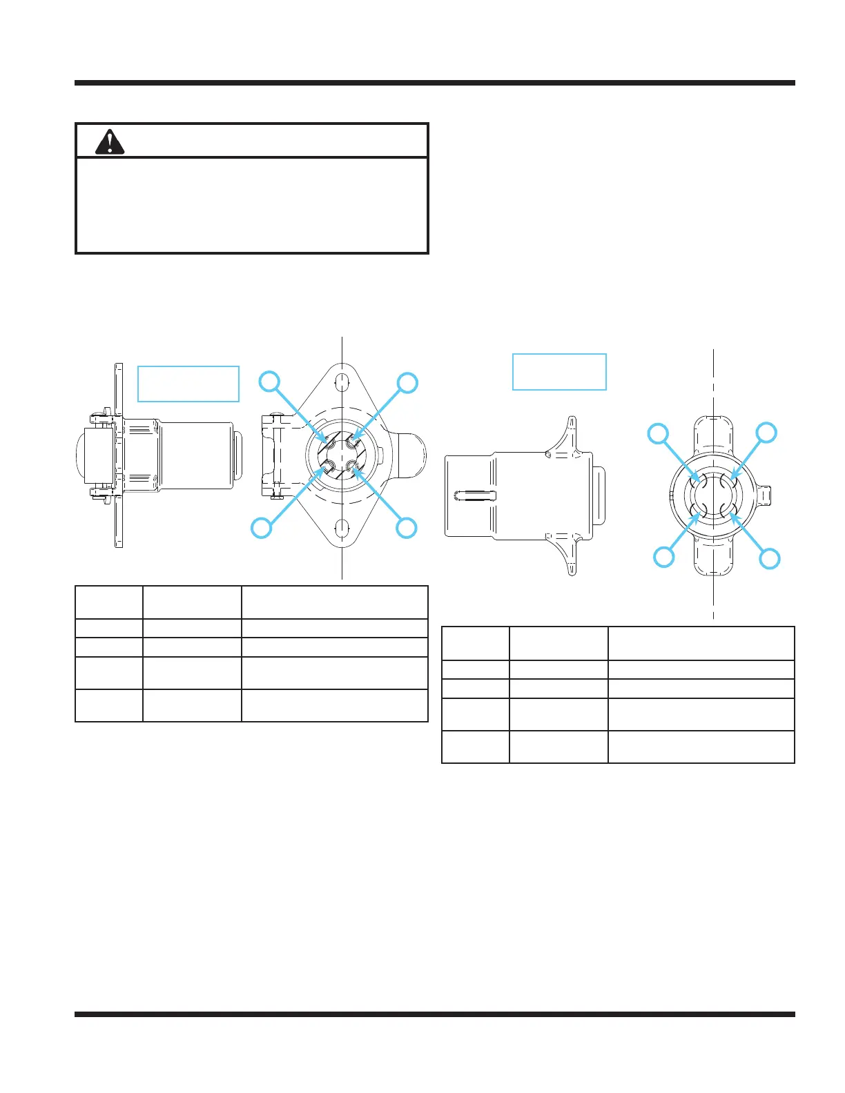
Wiring Diagram - Optional 30.0219 4-Pin Female Socket & 30.0218 4-Pin Male Plug
Attention
This connector (4-pin socket) is designed for use
with Ventrac original equipment only.
This connector (4-pin socket) is rated for 20 amp
maximum current draw. Engine alternator and/or bat-
tery capacity determine allowable continuous draw.
7
8
6
5
2
4
3
1
A B C D E F G H I J K
2/26/2014
swartz
30.0219
Socket, Trailer 4-Pin Female
Male Terminals
Released
Production Status
TITLE:
Drawing #
Drawn By:
Date:
Sheet Size:
Bin:
DIMENSION IN INCHES, DO NOT SCALE DRAWING.
Angular =
± 1°
Hole Locations/Geometry =
TOLERANCES:
Fractional =
.XXXX =
± 0.0005
.XXX =
± 0.005
NOTE: THIS DRAWING CONTAINS PROPRIETARY INFORMATION WHICH MAY NOT BE DISCLOSED TO OTHERS NOR USED FOR
MANUFACTURING WITHOUT WRITTEN PERMISSION FROM VENTURE PRODUCTS INC.
Material Description
Material Part #
ORRVILLE, OHIO 44667
Order Qty.
A
PRODUCTS INC.
Machine
± 0.015
.XX =
± 0.015
± 1/32
UNLESS OTHERWISE SPECIFIED
Admin
Special Notes
None
Last Printed Date 2/26/2014
Front View
Rear View
NOTE:
*This drawing is for Ventrac equipment only.
Custom applications are not the responsibility of Venture Products Inc,
* 20 amp Max Current draw
* Engine alternator and/or battery capacity determines allowable continuous draw
30.0219 4-Pin
Female Socket
Terminal Posi-
tion
Wire Color Function
1 White Positive (On/Off Switched)
2 Black Negative (Constant)
3 Green or Brown
Positive/Negative
(Momentary Switched Reversing)
4 Red
Positive/Negative
(Momentary Switched Reversing)
1
2 3
4
30.0218 4-Pin
Male Plug
7
8
6
5
2
4
3
1
A B C D E F G H I J K
2/26/2014
swartz
30.0218_00
Plug, Trailer 4-Pin Male
Female Terminals
Released
Production Status
TITLE:
Drawing #
Drawn By:
Date:
Sheet Size:
Bin:
DIMENSION IN INCHES, DO NOT SCALE DRAWING.
Angular =
± 1°
Hole Locations/Geometry =
TOLERANCES:
Fractional =
.XXXX =
± 0.0005
.XXX =
± 0.005
NOTE: THIS DRAWING CONTAINS PROPRIETARY INFORMATION WHICH MAY NOT BE DISCLOSED TO OTHERS NOR USED FOR
MANUFACTURING WITHOUT WRITTEN PERMISSION FROM VENTURE PRODUCTS INC.
Material Description
Material Part #
ORRVILLE, OHIO 44667
Order Qty.
A
PRODUCTS INC.
Machine
± 0.015
.XX =
± 0.015
± 1/32
UNLESS OTHERWISE SPECIFIED
Admin
Special Notes
None
Last Printed Date 2/26/2014
Front View
Rear View
NOTE:
*This drawing is for Ventrac equipment only.
Custom applications are not the responsibility of Venture Products Inc,
* 20 amp Max Current draw
* Engine alternator and/or battery capacity determines allowable continuous draw
Terminal Posi-
tion
Wire Color Function
1 Not Specied* Positive (On/Off Switched)
2 Not Specied* Negative (Constant)
3 Not Specied*
Positive/Negative
(Momentary Switched Reversing)
4 Not Specied*
Positive/Negative
(Momentary Switched Reversing)
* Refer to the part diagram in the attachment’s operator’s manual for specic wire color
and terminal position for each model.
1
2
3
4
30.0219 4-pin female socket is used in the
70.4104 12 Volt Front kit.
30.0218 4-pin male plug is used on attachments
to connect to the 30.0219 female socket on the
power unit.

 Loading...


