EasyManua.ls Logo

Vericom VC4000 - Page 92

Vericom VC4000
108 pages
Print Icon
To Next Page IconTo Next Page
To Previous Page IconTo Previous Page
Loading...
Sensor Input
VC4000 Manual
88
using a connector and solder sockets available from electronics
distributors.
BOM:
Description
Part Number
Molex SL 0.10” crimp housing, Version G
Molex, 50-57-9404
2x Box crimp terminals
Molex, 16-02-0102
Assembly instructions:
1. Solder two crimp terminals to one end of the wires.
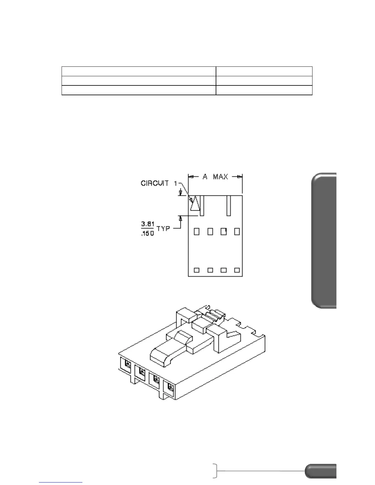
2. Place the positive wire terminal into pin 1 of the housing.
3. Place the ground wire terminal into pin 2 of the housing.
Figure 36: Molex crimp housing
Insert the black 4-pin connector of the cable into the External
Activation connector located in the back of the VC4000.

Table of Contents