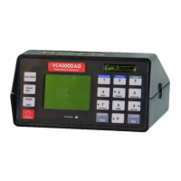
Figure 34: Brake pedal activation switch
The External Activation Input is used for starting the run when one of
the Reaction timers is used, when 12V is applied, or other input
switch is used. This switch allows the operator to bypass the Auto
Start G-Threshold. When using the external activation switch the
activation of the test will be either the switch or the G-Threshold
(0.2G default) whichever comes first. This switch may be used in the
Acceleration mode as well as the Braking mode.
When using the reaction timer switch the run will start the instant a
key is pressed and a lamp turns on.
When using the brake light switch or brake pedal switch the brake
run will start the instant the brake lights come on or the pedal is
touched, which is typically before the 0.2G threshold is reached.
Drag Factor (Average G) will be significantly less when using the
external activation switch because of the increase in time due to the
braking systems mechanical reaction time. The activation switch
may be connected to any 5 – 36VDC input.
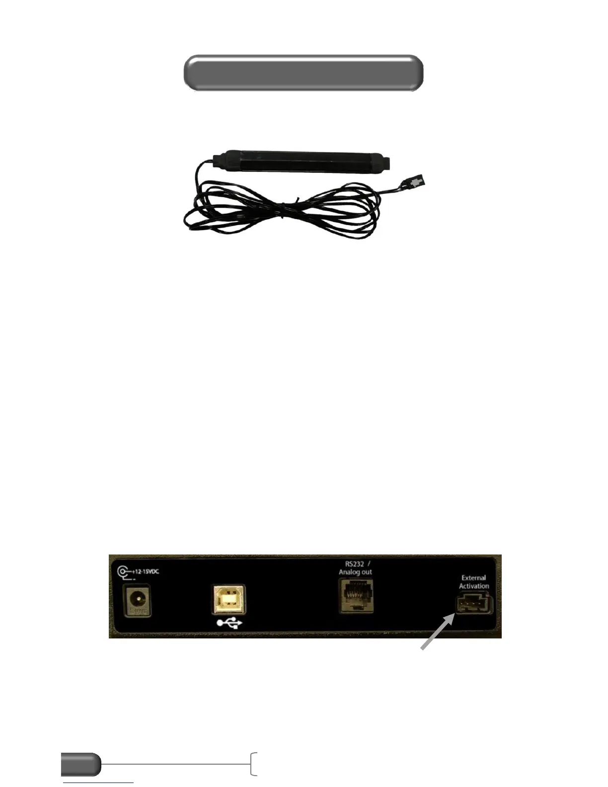
Figure 35: External Activation Switch input
To install the external activation input use an External Activation
cable available from Vericom Computers, Inc. Or make your own
 Loading...