Commander™ Site Controller Software Installation Guide 7
July 25, 2013
Rear Panel
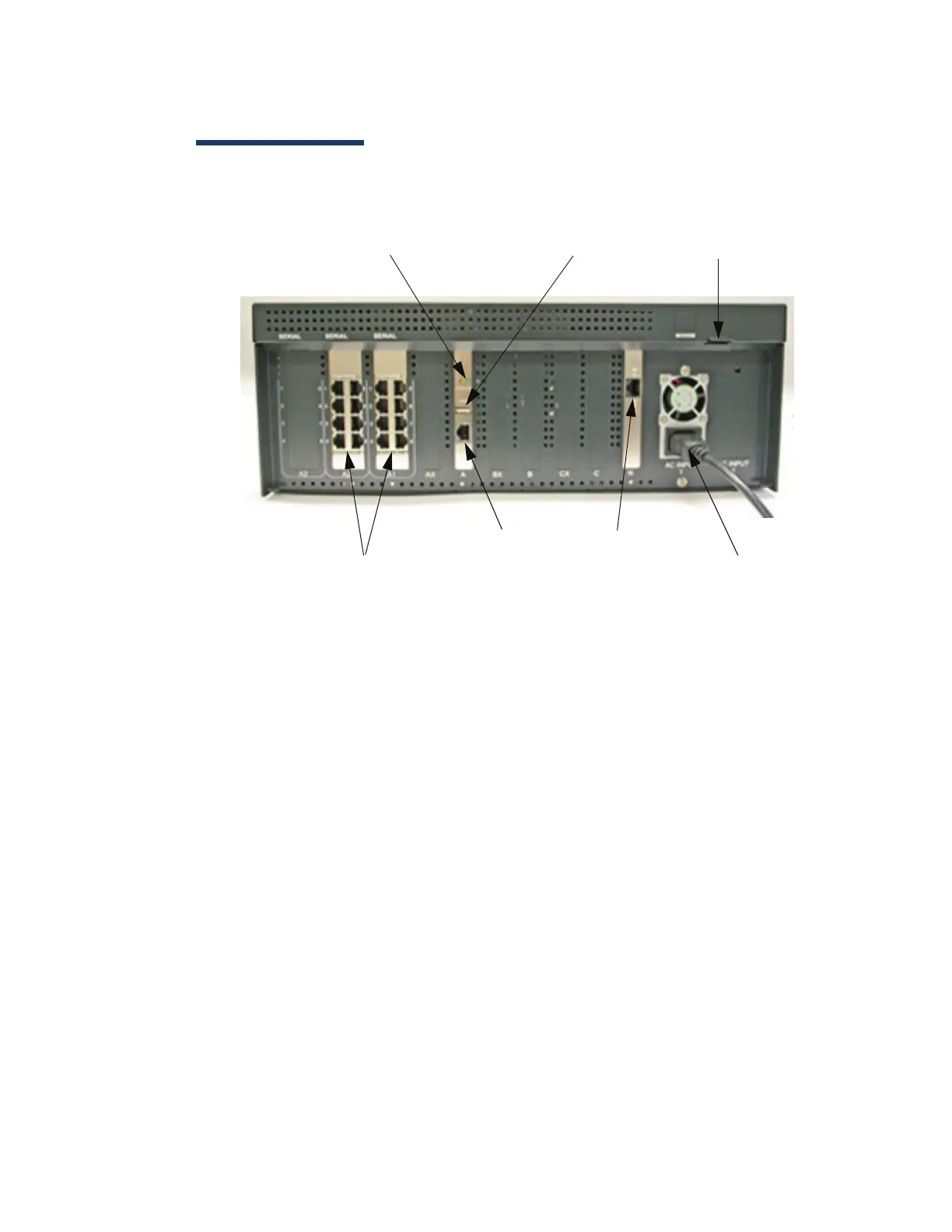
Figure 5: Commander Site Controller - Rear Panel
■ Device Ports for CPU A — Serial Port Connections
for CPU A, Banks A1 and A2
■ Activity LEDS for CPU A — LEDs flicker to show
LAN activity
■ USB Port — One USB 2.0 Port
■ LAN — For Card Processing Network
■ Modem Port — Connection used for dedicated
telephone line.
Note: Actual modem may not be present in all
configurations. Only UL listed USB Modem
permitted.
■ Ethernet Port — Ethernet port for POS and
external connectivity (WAN, VPN)
■ Power Connector — Connector for applying power
to the Site Controller
Device Ports for CPU A
LAN
Activity LEDs for CPU A
USB Port
Modem Port
Power Connector
Ethernet Port