10
Vermont Castings UVS27
4. The Firebox is completely assembled. The Burner and
Valve assembly require no adjustment, however, be
sure to remove the packaged logs from within the
firebox. If you have not yet done so, swing the two
cam latches outward on the screen frame to release it
from the unit. Remove the screen frame by lifting up
and away from firebox. Remove the box of logs from
inside the unit and set aside for later log placement.
5. Connect the gas supply line to the burner control valve
before you install the firebox. This may be a flexible
line, (not supplied), or hard plumbing.
6. Lift the firebox assembly as a unit and slide it back to
position it within the shell. The base of the firebox
should rest on the side support shelves as in Figures
5 and 6. The side plates interlock with the firebox by
use of a pair of steel tabs that engage with the ribs on
the base of the firebox. (Fig. 6) Properly positioned,
the firebox will be level and locked in place. If not,
adjust the levelling screws as required to keep the
entire assembly level.
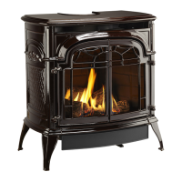
Install Optional Fan Kit
• Attach the fan to the firebox by engaging the upper
flange of the fan skirt under the lower edge of the
shroud and secure the skirt with the four screws and
one star washer provided. (Fig. 7, 8 )
• Feed the snapstat wire lead up between the inner
and outer rear shroud panels and secure the snapstat
to the upper right side of the inner shroud. (Fig. 9)
• Secure the snapstat wire harness to the shroud
panel using the wire tie provided.
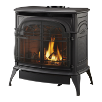
• Route the rheostat control switch and wire forward
under the stove. Use the wire tie to secure the fan and
rheostat wire harnesses together to the tubing under
the bottom heat shield.
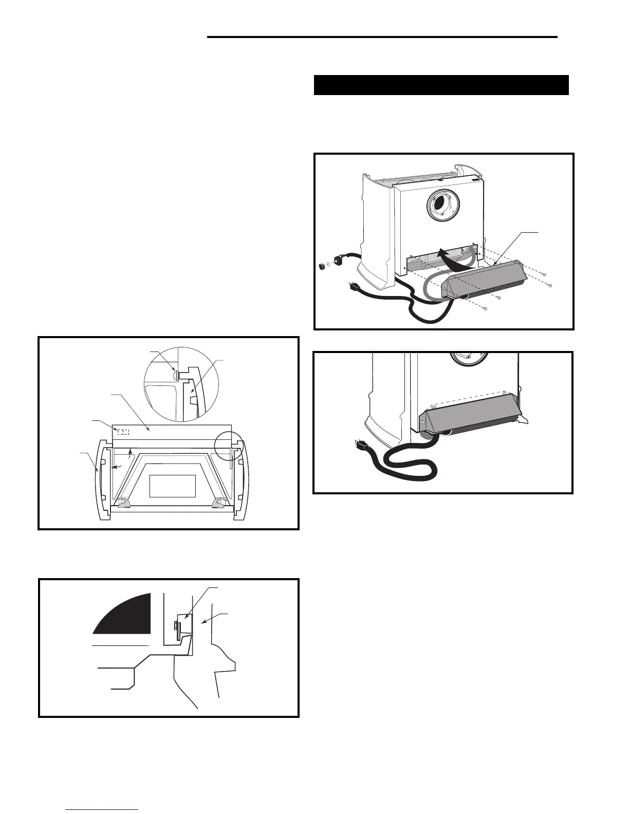
UVS27R/ Honeywell Miillivolt Valve: Install the
rheostat onto the control panel at the hole to the right
of the valve, as in Figure 10.
UVS27M/SIT Manual Valve: Install the rheostat onto
the bracket to the left of the valve.
Upper
Flange
Fig. 7 Place upper flange behind lower edge of shroud.
ST344
Fig. 8 Correct position of fan skirt installation.
ST345
Screw & Washer
Support Shelf
Side
Plate
Back Panel
Firebox
90°
Fig. 5 The sides must be at right angles to the Back Panel in
order for the firebox to fit properly.
Remote Switch
Knockout
ST106
Fig. 6 Install the Firebox Assembly. Be sure steel tabs engage
ribs on base of firebox.
Steel Tab
Side Plate
Support Shelf
Base
ST125
 Loading...