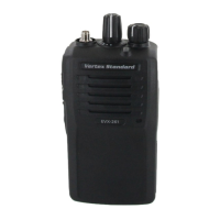
EVX-261 UHF Digital/Analog Transceiver Service Manual 1
Introduction
This manual provides the technical information necessary for servicing the
EVX-261
UHF Digi-
tal/Analog Transceiver.
Servicing this equipment requires expertise in handing surface-mount chip components. At-
tempts by non-qualifi ed persons to service this equipment may result in permanent damage not
covered by the warranty, and may be illegal in some countries.
Two PCB layout diagrams are provided for each double-sided board in this transceiver. Each side
of the board is referred to by the type of the majority of components installed on that side (“Side
A” or “Side B”). In most cases one side has only chip components (surface-mount devices), and
the other has either a mixture of both chip and leaded components (trimmers, coils, electrolytic
capacitors, ICs, etc.), or leaded components only.
As described in the pages to follow, the advanced microprocessor design of the
EVX-261
Trans-
ceiver allows a complete alignment of this transceiver to be performed without opening the case
of the radio; all adjustments can be performed from the front panel, using the “Alignment Mode”
menu.
While we believe the information in this manual to be correct, Vertex Standard assumes no li-
ability for damage that may occur as a result of typographical or other errors that may be present.
Your cooperation in pointing out any inconsistencies in the technical information would be ap-
preciated.
Important Note
This transceiver is assembled using Pb (lead) free solder, based on the RoHS specifi cation.
Only lead-free solder (Alloy Composition: Sn-3.0Ag-0.5Cu) should be used for repairs performed on this apparatus.
The solder stated above utilizes the alloy composition required for compliance with the lead-free specifi cation, and
any solder with the above alloy composition may be used.
Contents
Specifi cations................................................................................................................................................................. 2
Exploded View & Miscellaneous Parts ....................................................................................................................... 4
Parts List ....................................................................................................................................................................... 5
Block Diagram .............................................................................................................................................................. 6
Circuit Description ....................................................................................................................................................... 7
Alignment ...................................................................................................................................................................... 8
Cloning ........................................................................................................................................................................ 16
Main Unit (FR028100D) Circuit Diagram .............................................................................................................. 17
Vertex Standard LMR, Inc.
©2016 Vertex Standard LMR, Inc.
EC137U90C
UHF Digital/Analog Transceiver
EVX-261
Service Manual