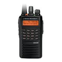
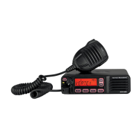
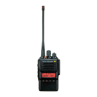
EVX-S24 UHF Digital/Analog Transceiver Service Manual 8
Circuit Description
1. Receiver System
1-1. Front-end RF Amplifi er
Incoming RF signal from the antenna passes through the
low-pass filter, antenna switching diode D1011/D1014
(both
1SS390
), and band-pass fi lter.
The fi ltered RF signal is applied to the amplifi er Q1033
(
MAX2373ETC+T
), then remove the undesired frequen-
cies by another band-pass fi lter.
The amplified RF signal is applied to the custom IC
Q1046 (
RODINIA
).
1-2. Demodulator
The custom IC Q1046 (
RODINIA
) converts a Base Band
signal by mixing the RF signal with the local signal, and
then the Base Band signal is demodulated by the another
section of the custom IC Q1046 (
RODINIA
).
The local signal is generated by the VCO which consists
of Q1036 (
BFR460L3
) and varactor diodes D1029/
D1030/D1031/D1032 (all
1SV279
).
1-3. Audio Amplifi er
The demodulated signal is adjusted the audio volume
level in the custom IC Q1046 (
RODINIA
). The adjusted
the audio signal is applied to the audio amplifi er Q1040
(
SA58637BS
). As a result, the audio signal provides up
to 500 mW (@4-ohm BTL) for internal speaker and exter-
nal speaker.
2. Transmitter System
2-1. MIC Amplifi er & Modulator
The speech signal from internal microphone MC2001 on
the DISPLAY Unit or external microphone J1005 on the
MAIN Unit is supplied to the custom IC Q1046 (
RO-
DINIA
), which modulates the speech signal to the FM or
digital signal.
2-2. Drive & Final Amplifi er Stages
The modulated signal from the custom IC Q1046 (
RO-
DINIA
) is buffered by Q1034 (
2SK3077
) and amplified
by driver amplifi er Q1026 (
RD01MUS2B
). The low level
transmit signal is then applied to Q1016 (
RD04LUS2
) for
fi nal amplifi cation up to 3 watts output power.
The transmit signal then passes through the antenna
switch D1009/D1053 (both
RN142S
) and is low-pass fi l-
tered to suppress away harmonic spurious radiation before
delivery to the antenna.
2-3. Automatic Transmit Power Control
The current detector Q1006-1 (
AD8566ARM
) detects the
current of the fi nal amplifi er Q1016 (
RD04LUS2
) and the
driver amplifi er Q1026 (
RD01MUS2B
), and converts the
current difference to the voltage difference.
The output from the current detector Q1006-1
(
AD8566ARM
) is compared with the reference voltage
and amplified by the power control amplifier Q1006-2
(
AD8566ARM
).
The output from the power control amplifier Q1006-2
(
AD8566ARM
) controls the gate bias of the driver ampli-
fi er Q1026 (
RD01MUS2B
) and the fi nal amplifi er Q1016
(
RD04LUS2
).
The reference voltage changes into two values (Transmit
Power High and Low) controlled by custom IC Q1046
(
RODINIA
).
3. PLL Frequency Synthesizer
The frequency synthesizer consists of VCO, TCXO
X1001, and the custom IC Q1046 (
RODINIA
).
The output frequency from TCXO X1001 is 19.2 MHz
and the tolerance is ±1.5 ppm in the temperature range
–22 °F to +140 °F (–30 °C to +60 °C).
3-1. VCO (Voltage Controlled Oscillator)
The VCO Q1036 (
BFR460L3
) generates a between 806-
940 MHz. The output from VCO Q1036 (
BFR460L3
) is
amplifi ed by buffer amplifi er Q1041 (
2SC5010
) and then
is supplied to the custom IC Q1046 (
RODINIA
).
The VCO frequency is divided into two by the dividing
section of the custom IC Q1046 (
RODINIA
) in order to
become a true receiving or transmitting frequency.
In the reception, the RF signal convert a Base Band signal
by mixing with the divided VCO signal, and then supplied
to the demodulator section of the custom IC Q1046 (
RO-
DINIA
), described previously.
In the transmission, the divide VCO frequency is modu-
lated to the FM (or digital) in the custom IC Q1046 (
RO-
DINIA
), and then is supplied to the transmitter section
described previously.
3-2. Varactor Control Voltage
The tuning voltage (VCV) of the VCO establishes the
lock range of VCO by controlling the cathode of varactor
diode D1029, D1030, D1031 and D1032 (all
1SV279
).
from the custom IC Q1046 (
RODINIA
).
3-3. PLL
The main constitution product of the PLL is equipped all
with in the custom IC Q1046 (
RODINIA
), so that all pro-
cessing regarding the frequency control is performed in
the custom IC Q1046 (
RODINIA
).
 Loading...


