EasyManua.ls Logo

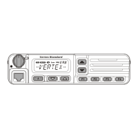
Vertex Standard VM-3500E User Manual

Vertex Standard VM-3500E
68 pages
To Next Page IconTo Next Page
Page #1 background imageLoading...
Page #1 background image
Page 1VM-3500E
VM-3500E
25 Watt VHF/FM
Marine Transceiver
Owner's Manual
Oversized alphanumeric LCD, knobs and keys
30 W Loud Hailer with listen back and 4 fog horns, Bells & Whistles
Direct keypad entry of a channel using the keypad
Removable ClearVoice speaker microphone with 16/9 key and channel
selection
Display shows channel names, and repeats GPS information
8
Capable of connecting an optional enhanced RAM+ second station re-
mote microphone
DSC distress call automatically broadcasts lat/long and vessel ID
8
DSC position request function and NMEA data input/output to connect to
GPS Plotter
8
Versatile user-programmable Scanning, Priority Scan and Dual Watch
One-button access to Channel 16 and 9
8 with GPS attached

Table of Contents

Questions and Answers:

Vertex Standard VM-3500E Specifications

General IconGeneral
BrandVertex Standard
ModelVM-3500E
CategoryTransceiver
LanguageEnglish

Summary

GENERAL INFORMATION

PACKING LIST

Lists items included in the transceiver package.

OPTIONS

Lists optional accessories available for the transceiver.

INSTALLATION NOTE

GETTING STARTED

ABOUT VHF RADIO

Explains the basics of VHF radio operation and range.

SELECTING AN ANTENNA

Provides guidance on choosing the right antenna for marine use.

INSTALLATION

LOCATION

Details recommended placement for the transceiver.

ELECTRICAL CONNECTIONS

Explains how to connect power and antenna to the unit.

ACCESSORY CABLE

Describes connections for external speakers and GPS units.

CONNECTION OF GPS WITH NMEA OUTPUT

Guides on linking a GPS receiver via NMEA.

CHECKING GPS CONNECTIONS

How to verify a successful GPS connection.

CHANGING THE GPS TIME

Instructions to set local time based on GPS data.

CHANGING THE TIME LOCATION

How to switch between UTC and local time display.

CHANGING COG TO TRUE OR MAGNETIC

Customizes GPS Course Over Ground display.

OPTIONAL MMB-84 FLUSH MOUNT INSTALLATION

Details for flush mounting the transceiver.

OPTIONAL ENHANCED RAM+ SECOND STATION MIC INSTALLATION

Steps for installing an optional remote microphone.

CONTROLS AND INDICATORS

BASIC OPERATION

RECEPTION

How to receive signals and adjust settings.

TRANSMISSION

Procedures for transmitting voice messages.

TRANSMIT TIME - OUT TIMER (TOT)

Explains the automatic transmit timer function.

SIMPLEX/DUPLEX CHANNEL USE

Information on channel operation modes.

INTERNATIONAL, USA, AND CANADA MODE

How to select country-specific operating modes.

NOAA WEATHER CHANNELS

Instructions for accessing NOAA weather broadcasts.

NOAA WEATHER ALERT

Details on receiving weather alert notifications.

EMERGENCY (CHANNEL 16 USE)

Procedure for making distress calls on Channel 16.

CALLING ANOTHER VESSEL (CHANNEL 16 OR 9)

How to hail and contact other vessels.

DUAL WATCH (TO PRIORITY CHANNEL)

Monitors two channels simultaneously.

SCANNING

Selecting the Scan Type

How to choose between Memory and Priority scan modes.

Memory Scanning (M-SCAN)

Steps to program and start memory scanning.

Priority Scanning (P-SCAN)

How to use priority scanning with a designated channel.

PA/FOG OPERATION

Operating the PA HAIL mode

Instructions for using the public address/hailer function.

Operating the FOG HORN mode

How to activate fog horn signals and patterns.

NAVIGATION INDICATION

LCD DIMMER

INTERCOM OPERATION

Communication

Enables voice communication between the transceiver and RAM+ Mic.

Calling

How to initiate a call to another station.

VOICE SCRAMBLER

DIGITAL SELECTIVE CALLING

GENERAL

Introduction to DSC and its purpose in maritime safety.

MARITIME MOBILE SERVICE IDENTITY (MMSI)

Explains MMSI and how to program it into the radio.

DSC DISTRESS CALL

Details on sending and receiving distress alerts.

ALL SHIPS CALL

How to send broadcast calls to all vessels.

INDIVIDUAL CALL

How to contact specific vessels using DSC.

GROUP CALL

How to contact groups of vessels via DSC.

Manual Setting of the GPS Location (LAT/LOG)

Manually inputting vessel position for DSC.

RADIO SETUP

LCD CONTRAST

Adjusts display visibility for different viewing angles.

TIME OFFSET

Sets the time difference between local and UTC.

TIME LOCATION

Selects display format for local or UTC time.

TRUE MAGNETIC CHANGE (NAV display)

Configures GPS COG display as True or Magnetic.

PRIORITY CHANNEL SET

Designates a channel as the priority for scanning.

SCAN TYPE

Selects between Memory and Priority scan modes.

SCAN RESUME TIME

Sets the delay before scanning resumes after a transmission.

KEY BEEP (ON/OFF)

Enables or disables button press audible feedback.

CHANNEL NAME CHANGE

Allows renaming of channels for easier identification.

UNIT NAMING

Assigns names to the radio and optional RAM+ Mic.

FOG ALERT TONE FREQUENCY

Sets the frequency for fog horn alert tones.

ENHANCED RAM+ MIC OPERATION

RAM+ MIC CONTROLS

Describes the functions of the RAM+ microphone buttons.

INTERCOM OPERATION

Communication

Enables voice communication between the transceiver and RAM+ Mic.

Calling

How to initiate a call to another station.

PA/FOG OPERATION

Operating the PA / Hailer

Instructions for using the public address/hailer function.

Operating the FOG Horn

How to activate fog horn signals and patterns.

DSC/RADIO SETUP MODE

MAINTENANCE

GENERAL

General precautions to prevent damage to the transceiver.

TROUBLESHOOTING CHART

Lists common problems and their solutions.

CHANNEL ASSIGNMENTS

SPECIFICATIONS

GENERAL SPECIFICATIONS

General technical specifications of the transceiver.

TRANSMITTER

Technical details of the transmitter section.

RECEIVER

Technical details of the receiver section.

APPENDIX

FOG HORN TIMING CHART

Details timing patterns for fog horn signals.

Related product manuals