Do you have a question about the Vertex Standard Pilot VXA-210 and is the answer not in the manual?
Explains FCC RF exposure compliance for occupational use and guidelines for safe operation.
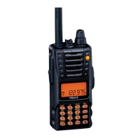
Introduces the transceiver, its capabilities, and congratulates the user.
Describes controls located on the top panel: Antenna Jack, Power/Volume, Busy/TX Lamp, Dial Selector.
Details controls and indicators on the front panel: LCD, Loudspeaker, Microphone, Keypad, Battery Latch.
Explains the various indicators and fields shown on the LCD display, including navigation and status icons.
Details the primary and secondary functions of the keypad buttons.
Describes controls located on the left side: PTT, Monitor, and Lamp switches.
Details connectors located on the right side: MIC/EAR Jack and External DC Jack.
Lists safety precautions for using the radio, including DC connections and battery handling.
Provides step-by-step instructions for installing and removing the battery pack.
Explains the procedure for charging the Ni-Cd battery pack before first use.
Describes the low battery indicator and advice on recharging and battery life.
Explains how to install the optional alkaline battery case.
Outlines initial steps and a quick guide to turning on and selecting a frequency.
Details methods for setting frequencies: VFO, Memory, Book, and Weather Channels.
Explains how to transmit, return to receive mode, and receive weather broadcasts.
Explains how to scan and select weather channels.
Describes Monitor Key for weak signals and ANL for noise reduction.
Explains temperature display and how to activate/deactivate the lock function.
Explains the Receive Battery Saver feature and its settings for power conservation.
Describes how to turn the keypad beeper on or off.
Provides steps to calibrate the thermometer setting.
Explains barometer and altimeter offset correction for accurate readings.
Steps to measure pressure/altitude and operate in Weather Sensor Mode.
Shows the displays for temperature, pressure, altitude, and density altitude.
Provides steps to store frequencies into memory channels.
Explains the main memory system for storing, labeling, and recalling channels.
Details how to recall stored memory channels and change display title structure.
Describes scanning modes (VFO, Memory, Weather) and automatic scanner operation.
Details how to manually scan frequencies in the NAV band.
Explains how to designate channels to be skipped during scanning.
Explains the Dual Watch feature for checking activity on a priority channel.
Provides steps to start and stop the Dual Watch feature.
Describes additional features of Priority Dual Watch.
Provides steps to start and stop the Priority Dual Watch feature.
Illustrates general VOR equipment and frequency bands (COM and NAV).
Illustrates the display interface in DVOR and CDI modes.
Explains how to automatically select the DVOR mode in the NAV band.
Describes the TO/FROM flag and how to toggle display information.
Details how the radio indicates deviation from a direct course to a VOR station.
Illustrates display scenarios for aircraft on course and off course.
Explains how to configure for desired course indication and ABCS mode.
Details how to cross-check position using two VOR stations.
Explains the split operation feature for transmitting on COM and receiving on NAV.
Steps to activate Field Programming Mode and store data into Book Memory.
Explains how to use the menu system to customize radio configuration.
Lists menu items, functions, defaults, and provides steps to clear memory channels.
Covers scan-resume, lamp, keypad beep, and battery saver settings.
Covers illumination, clock shift, priority, microphone, beep, and emergency settings.
Allows calibration of the internal thermometer and barometer.
Provides step-by-step instructions for installing the SU-1 unit.
Notes the supplemental nature of SU-1 features and not a substitute for critical navigation devices.
Lists accessories supplied with the radio and optional accessories available for purchase.
Illustrates external antenna connection and headset setup with PTT switch.
Lists general, receiver, and transmitter technical specifications.
Advises contacting a dealer first for operational difficulties and provides service center info.
Outlines the process for sending the radio for repair, including warranty details.
Details repair turnaround times, cost estimates, and shipping methods.
| Modulation | AM |
|---|---|
| Channel Spacing | 25 kHz |
| Operating Voltage | 7.2 V DC |
| Frequency Range | 118.000 to 136.975 MHz |
| Voltage | 7.2 V DC |