VXA-210 PILOT OPERATING MANUAL
5
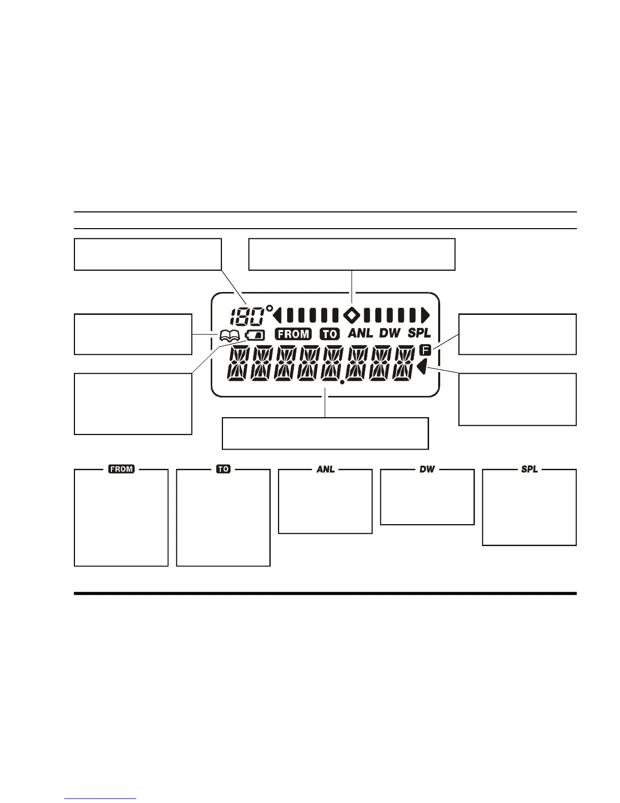
CONTROLS & CONNECTORS
(
LCD DISPLAY
)
This field displays the course
heading in degrees. See page 33.
This is the Course Deviation Indicator, used
during VOR Navigation. See page 32.
This icon indicates that
the “Book” Memory Bank
is in use. See page 15.
This icon is the “Low Bat-
tery” indicator, which
blinks when the battery
voltage becomes too low
for proper operation.
These digits provide frequency or alphanumeric
information about the channel you are using.
This indicator confirms
that Secondary Key Func-
tion is active. See page 6.
This indicator confirms
that this channel will be
skipped during scan. See
page 29.
This icon is used
during VOR naviga-
tion, to indicate that
the displayed infor-
mation is based on
a course from the
VOR station. See
page 33.
This icon is used
during VOR naviga-
tion, to indicate that
the displayed infor-
mation is based on
a course to the VOR
station. See page
33.
This indicator con-
firms that the AUTO-
MATIC NOISE LIMITER is
activated. See page
18.
This indicator con-
firms that D UAL
WATCH is active. See
page 30.
This indicator con-
firms that the “Split”
(Duplex) mode is
activated during
VOR operation. See
page 38.
 Loading...