EasyManua.ls Logo

Vertex Standard VX-4107 - User Manual

Vertex Standard VX-4107
10 pages
Print Icon
To Next Page IconTo Next Page
Loading...
FCC ID: K6610354640
IC ID: 511B-10354640
Alignment
1
/
10
Vertex Standard Co., Ltd.
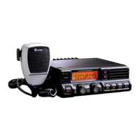
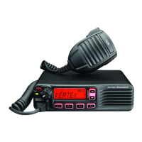
VX-4107/4207 Alignment
Introduction
The VX-4100/4200 series are carefully aligned at the factory for the specified
performance across the frequency range specified for each version. Realignment should
therefore not be necessary except in the event of a component failure, or altering version type.
All component replacement and service should be performed only by an authorized Vertex
Standard representative, or the warranty policy may be void.
The following procedures cover the sometimes critical and tedious adjustments that are
not normally required once the transceiver has left the factory. However, if damage occurs and
some parts subsequently are placed, realignment may be required. If a sudden problem occurs
during normal operation, it is likely due to component failure; realignment should not be done
until after the faulty component has been replaced.
We recommend that servicing be performed only by authorized Vertex Standard service
technicians who are experienced with the circuitry and fully equipped for repair and alignment.
Therefore, if a fault is suspected, contact the dealer from whom the transceiver was purchased
for instructions regarding repair. Authorized Vertex Standard service technicians realign all
circuits and make complete performance checks to ensure compliance with factory
specifications after replacing any faulty components.
Those who do undertake any of the following alignments are cautioned to proceed at
their own risk. Problems caused by unauthorized attempts at realignment are not covered by
the warranty policy. Also, Vertex Standard reserves the right to change circuits and alignment
procedures in the interest of improved performance, without notifying owners.
Under no circumstances should any alignment be attempted unless the normal function
and operation of the transceiver are clearly understood, the cause of the malfunction has been
clearly pinpointed and any faulty components replaced, and realignment determined to be
absolutely necessary.
The following test equipment (and thorough familiarity with its correct use) is necessary
for complete realignment. Correction of problems caused by misalignment resulting from use of
improper test equipment is not covered under the warranty policy. While most steps do not
require all of the equipment listed, the interactions of some adjustments may require that more
complex adjustments be performed afterwards.
Do not attempt to perform only a single step unless it is clearly isolated electrically from
all other steps. Have all test equipment ready before beginning, and follow all of the steps in a
section in the order presented.
Question and Answer IconNeed help?

Do you have a question about the Vertex Standard VX-4107 and is the answer not in the manual?

Overview

The VX-4107/4207 series devices are transceivers designed for reliable communication across a specified frequency range. They are factory-aligned to ensure optimal performance, and realignment is generally not necessary unless a component fails or the version type is altered. All servicing and component replacement should be performed by an authorized Vertex Standard representative to maintain warranty validity.

Function Description:

The transceivers facilitate two-way radio communication. They are equipped with various alignment parameters that can be adjusted using a dedicated alignment tool and software on a PC. These parameters include:

  • VCO Tune Voltage (RX/TX VCO): Aligns the tune voltage for both the receiver and transmitter Voltage Controlled Oscillators. This is an automated alignment process.
  • PLL Reference Frequency (Frequency): Aligns the reference frequency for the Phase-Locked Loop, crucial for stable frequency operation. This requires the radio to transmit and the frequency to be set on a frequency counter.
  • RX Sensitivity (RX Tune): Aligns the Receiver Band Pass Filter (BPF) to optimize sensitivity. This adjustment requires a signal generator.
  • Squelch (SQL): Aligns various squelch levels, including Noise SQL Tight, Noise SQL Threshold, and RSSI SQL for both Wide and Narrow channels, to control receiver muting based on signal strength or noise.
  • TX Power: Aligns the output power levels for transmission (High, Low3, Low2, Low1 settings). This involves transmitting and adjusting the power using a power meter.
  • Modulation Balance: Aligns the balance between VCO Modulation and Reference Modulation. This is a critical adjustment that involves setting audio generator output at different frequencies (40 Hz and 3 kHz) and adjusting deviation.
  • Maximum Deviation (MAX DEV W/N): Aligns the maximum deviation for both Wide and Narrow channels.
  • Sub-Audio Deviation (CTCSS/DCS W/N): Aligns the deviation for CTCSS (Continuous Tone-Coded Squelch System) and DCS (Digital Coded Squelch) sub-audio tones for both Wide and Narrow channels.
  • MIC Gain: Aligns the microphone gain, requiring a Tuning Interface BOX (FRB-4).
  • Sequential Tone Deviation: Aligns the deviation for 2-Tone, 5-Tone, and DTMF sequential tones.
  • Low Battery Level: Aligns the voltage threshold for the low battery warning.
  • EEPROM Protect Level: Aligns the voltage level for EEPROM protection.

Important Technical Specifications:

  • Frequency Range: The devices are aligned for specific frequency ranges, with examples given for UHF-A(VTX) at Band-LOW (400.100MHz), Band-MID (435.100MHz), and Band-HIGH (469.900MHz).
  • Power Output: High power versions can be 50 W (VHF) or 45 W (UHF), while Mid power versions are 25 W. Lower power settings (Low3, Low2, Low1) are also available, ranging from 25 W down to 1 W depending on the version.
  • Deviation: Target deviation for Wide channels is 4.2 kHz, and for Narrow channels, it is 2.1 kHz. Sub-audio deviation targets are 0.6 kHz (Wide) and 0.4 kHz (Narrow).
  • Power Supply: Requires a regulated DC Power Supply (standard 13.6 V DC, 15 A).
  • Audio Output: The AF Dummy Load specification indicates "Audio output is BTL output."

Usage Features:

  • PC-Controlled Alignment: The alignment process is primarily controlled via an IBM PC/compatible computer running Microsoft Windows95 or later, using Vertex Standard VPL-1 Connection Cable and CE59 Programming software.
  • Alignment Mode: The transceiver enters a special "Alignment mode" where normal operation is suspended, and all actions are remote-controlled by the PC.
  • Basic Alignment Mode: This mode allows for aligning multiple parameters with three points (low edge, center, high edge), except for VCO, RX Tune, and Mod Balance. Values can be adjusted using arrow keys, direct number input, or mouse drag.
  • Channel Fine Alignment Mode: This mode allows for aligning specific parameters (RX Sensitivity, TX Power High/Low, Modulation Balance, Maximum Deviation, Sub-Audio Deviation) per channel, offering granular control.
  • Data Management: The alignment tool allows for data upload from the radio, alignment of data, and data download back to the transceiver. Temporary data is updated upon confirmation, and final data is downloaded to the transceiver.

Maintenance Features:

  • Preventive Realignment: Realignment is generally not required unless there's a component failure or a change in version type.
  • Fault Diagnosis: If a problem occurs, it's likely due to component failure, and realignment should only be attempted after replacing the faulty component.
  • Authorized Servicing: Servicing should be performed by authorized Vertex Standard service technicians who are experienced and properly equipped. Unauthorized attempts at realignment may void the warranty.
  • Environmental Conditions: Correct alignment requires the ambient temperature to be stable between 20 and 30°C (68 - 86 °F) and the test equipment to be thoroughly warmed up.
  • Structured Alignment Procedure: The manual emphasizes following all alignment steps in the presented order and not attempting single steps in isolation unless electrically isolated.
  • Test Equipment: A comprehensive list of required test equipment is provided, including RF Signal Generator, Deviation Meter, In-line Wattmeter, RF Dummy Loads (50 Ω and 4 Ω/12 W AF), Regulated DC Power Supply, Frequency Counter, Audio Signal Generator, AC/DC Voltmeters, UHF Sampling Coupler, and the PC with specific software and cable. Proper familiarity with this equipment is essential.

Vertex Standard VX-4107 Specifications

General IconGeneral
BrandVertex Standard
ModelVX-4107
CategoryTransceiver
LanguageEnglish

Related product manuals