Do you have a question about the Vertex Standard VX-4600 Series and is the answer not in the manual?
Provides the manual's purpose and scope for servicing the transceiver, including technical information.
Warns against unqualified personnel and potential damage or legal issues from improper servicing.
Specifies the use of lead-free solder for repairs according to RoHS standards for this apparatus.
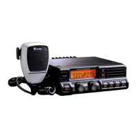
Details frequency ranges, channel count, power supply, dimensions, and weight of the transceiver.
Lists receiver sensitivity, selectivity, and transmitter performance by TIA/EIA standards.
Lists receiver sensitivity, selectivity, and transmitter performance by EN 300 086 standards.
Details the purpose and function of each pin on the 15-pin DSUB accessory connector.
Describes pins for 13.6V DC output, external PTT, and TRX switching control.
Explains pins for programmable accessory ports and the ignition sense feature.
Illustrated breakdown of parts for the VX-4500 front panel assembly.
Illustrated breakdown of parts for the VX-4600 front panel assembly.
Lists accessories included with the transceiver, with part numbers and quantities.
Illustrates the overall functional architecture of the main transceiver unit.
Shows the interface and block diagrams for front panel and separate units.
Explains the RF signal path from antenna input through the receiver stages.
Details the operation of squelch circuit and noise detection logic.
Covers the transmitter path, power amplification, and PLL synthesizer operation.
Lists necessary tools for calibration and provides diagrams for test equipment setup.
Explains how to use the CE115 software and enter the alignment mode.
Guides on adjusting VCO, PLL Frequency, RX Sensitivity, and Squelch.
Covers setting TX Power, Maximum Deviation, and Modulation Balance.
Details alignment for CTCSS, DCS, DTMF, VOX, TX MSK, and AF Output levels.
Overviews of FVP-35, DVS-8, and VT-60F/FS modules and their capabilities.
Instructions for physically installing optional units into the transceiver.
Detailed list of parts and components for the MAIN Unit PCB.
Detailed list of parts and components for the FRONT-A Unit PCB.
Detailed list of parts and components for the FRONT-B Unit PCB.
Detailed schematic diagram illustrating the DVS-8 optional voice storage unit.
Illustrates the placement of components on both sides of the DVS-8 circuit board.
| Modulation | 16K0F3E, 11K0F3E |
|---|---|
| Voltage | 7.4 V DC |
| Operating Temperature | -30°C to +60°C |
| Channel Spacing | 12.5 / 25 kHz |
| Operating Voltage | 7.4V DC |