EasyManua.ls Logo

Vertex Standard VX-210AU User Manual

Vertex Standard VX-210AU
42 pages
To Next Page IconTo Next Page
Page #1 background imageLoading...
Page #1 background image
1
Contents
©2002 VERTEX STANDARD CO., LTD. Printed in Japan.
UHF Band
Service Manual
VX-210AU
Introduction
The Vertex VX-210AU is a compact hand portable trans-
ceiver for the UHF land mobile band that offers the conve-
nience of small size, light weight, and simple operation.
The VX-210AU can be simply programmed by your
Vertex Dealer with up to 16 channels for single and split
frequency operation. The VX-210AU provides up to 5
watts of RF output power and includes a flexible quick-
connect antenna.
The transceiver and Ni-Cd battery packs are construct-
ed of thick high-impact polycarbonate plastic, with spe-
cial attention paid by the designers to tight seals and rug-
gedness, assuring years of reliable operation even in harsh
environments.
The following pages describe the operation, features
and accessories of the VX-210AU. With proper care and
operation, the transceiver will provide many years of re-
liable communications.
Operating Manual Reprint .........................................................................................................................................2
Specifications ...............................................................................................................................................................5
Cloning..........................................................................................................................................................................6
Exploded View & Miscellaneous Parts .....................................................................................................................7
Block Diagram ..............................................................................................................................................................8
Circuit Description ......................................................................................................................................................9
Alignment ...................................................................................................................................................................11
Board Units (Schematics, Layouts & Parts)
MAIN Unit .............................................................................................................................................................13
SW Unit ................................................................................................................................................................... 37
Optional Board Units (Schematics, Layouts & Parts)
VTP-50 VX-Trunk Unit .......................................................................................................................................... 38
FVP-25 Encryption / DTMF Pager Unit ................................................................................................................ 40
EC020U90A
VERTEX STANDARD CO., LTD.
4-8-8 Nakameguro, Meguro-Ku, Tokyo 153-8644, Japan
VERTEX STANDARD
US Headquarters
10900 Walker Street, Cypress, CA 90630, U.S.A.
International Division
8350 N.W. 52nd Terrace, Suite 201, Miami, FL 33166, U.S.A.
YAESU EUROPE B.V.
P.O. Box 75525, 1118 ZN Schiphol, The Netherlands
YAESU UK LTD.
Unit 12, Sun Valley Business Park, Winnall Close
Winchester, Hampshire, SO23 0LB, U.K.
VERTEX STANDARD HK LTD.
Unit 5, 20/F., Seaview Centre, 139-141 Hoi Bun Road,
Kwun Tong, Kowloon, Hong Kong

Other manuals for Vertex Standard VX-210AU

Question and Answer IconNeed help?

Do you have a question about the Vertex Standard VX-210AU and is the answer not in the manual?

Vertex Standard VX-210AU Specifications

General IconGeneral
BrandVertex Standard
ModelVX-210AU
CategoryTransceiver
LanguageEnglish

Summary

VX-210AU Introduction and Operation

Introduction to VX-210AU

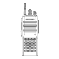
Overview of the Vertex VX-210AU UHF transceiver.

Controls and Connectors Overview

Details the physical controls and indicators of the transceiver.

Battery Pack Management

Covers installation, removal, and handling of the battery pack.

Operation Quick Start Guide

Guides users through initial setup and basic operational steps.

Programmable ACC Button Functions

Explains the programmable ACC button assignments and usage.

Detailed Operating Functions

Describes functions like Monitor, Squelch OFF, Low Power, Scan, Follow-Me Scan, Dual Watch.

Advanced Operating Features Explained

Covers Talk Around, Call/Reset, Speed Dial, TX Save Off, ACC 1, ACC 2.

Available Accessories and Options

Lists available accessories and optional units for the transceiver.

VX-210AU Specifications

VX-210AU Cloning Procedure

VX-210AU Exploded View and Parts

VX-210AU Block Diagram

VX-210AU Circuit Description

Receive Signal Path Details

Details the RF signal flow from antenna to audio output.

Squelch Control Mechanism

Explains the squelch circuitry and its operation.

Transmit Signal Path Details

Describes the audio signal path during transmission.

Automatic Transmit Power Control

Explains the mechanism for controlling transmit power output.

Transmit Inhibit and Spurious Suppression

Covers features that prevent transmission and reduce unwanted emissions.

PLL Frequency Synthesizer Operation

Describes the Phase-Locked Loop circuitry for frequency generation.

PTT Activation Process

Details how the PTT switch activates the transmit mode.

VX-210AU Alignment Procedures

Required Test Equipment for Alignment

Lists necessary tools and equipment for alignment.

PLL VCV Adjustment Procedure

Details the voltage adjustment for the PLL Varactor Control.

Transmitter Alignment Steps

Covers alignment of PLL reference frequency, output power, and modulation.

Receiver Alignment Steps

Details alignment for sensitivity and RSSI.

Main Unit Schematics and Parts

Main Unit Circuit Diagram

Provides the detailed circuit schematic for the main unit.

Main Unit Parts Layout

Illustrates component placement on the main unit board.

Main Unit Parts List

A comprehensive list of all components used in the Main Unit.

SW Unit Schematics and Parts

SW Unit Circuit Diagram

Shows the circuit diagram for the SW unit.

SW Unit Parts List

Lists the components for the SW unit.

Optional Board Units

VTP-50 VX-Trunk Unit Details

Details the circuit diagram, parts layout, and list for the VTP-50 VX-Trunk Unit.

FVP-25 Encryption / DTMF Pager Unit Details

Provides circuit diagram, parts layout, and list for the FVP-25 unit.

Related product manuals