Do you have a question about the Vertex Standard VX-2000V and is the answer not in the manual?
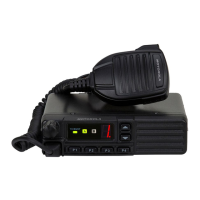
Provides technical information for servicing the VX-2000V VHF Land Mobile transceiver.
Connection point for the microphone.
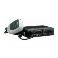
CHANNEL Numbered Indicators & Button for channel selection.
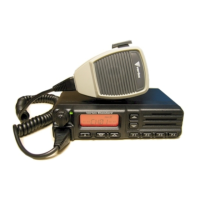
CHANNEL Selector Buttons, Numeric Display, SEL/PRI, SCAN buttons.
MONI, A Button, VOLUME/POWER Knob, TX/BUSY Lamp.
P Indicator and E Indicator for status.
Connects the supplied DC power cable to this 2-pin connector.
Connects the 50-ohm coaxial feedline using a "UHF" type plug.
Connects an external loudspeaker via a 3.5-mm miniature phone jack.
Provides external audio, PTT, squelch, and receive audio signals.
Turn the VOLUME/POWER knob clockwise to turn on the radio.
How to change channels on 4-channel and 40-channel versions.
Adjust volume using the VOLUME/POWER knob.
How to transmit using the PTT switch and TX/BUSY indicator.
Busy Channel Lock-Out and Automatic Time-Out features.
Activating and configuring scanning modes.
Using the MONI button to defeat coded or noise squelch.
Detailed functions for each pin of the DSUB connector.
General specifications of the transceiver.
Receiver performance specifications.
Transmitter performance specifications.
Visual breakdown and parts list for the transceiver.
Block diagram for the 4-channel front panel.
Block diagram for the 40-channel front panel.
Shows the functional blocks of the Main Unit.
Shows how the units connect for the 4-channel version.
Shows how the units connect for the 40-channel version.
Traces the RF signal from antenna to audio output.
Explains how the squelch circuitry operates.
Describes the signal path from microphone to antenna.
Automatic power control, transmit inhibit, and spurious suppression.
Explanation of the Phase-Locked Loop circuitry.
How the PTT switch activates transmission.
CHANNEL button function for channel selection and display.
UP/DOWN buttons function for channel selection and display.
List of necessary test equipment for alignment.
Steps before starting alignment, including software and temperature.
Checking the varactor control voltage for the PLL.
Adjusting TC1001 for PLL reference frequency.
Adjusting VR1002/VR1003 for output power levels.
Adjusting VR1001/VR1004 for deviation levels.
Adjusting VR1006 to set squelch threshold.
Reloading original channel data after alignment.
Schematic for the MAIN Unit (Lot. 1~).
Component layout for the MAIN Unit (Lot. 1~).
Schematic for the MAIN Unit (Lot. 5~).
Component layout for the MAIN Unit (Lot. 5~).
Schematic for the MAIN Unit (Lot. 19~).
Component layout for the MAIN Unit (Lot. 19~).
List of capacitors for the MAIN Unit.
List of diodes, filters, and thermistors for the MAIN Unit.
List of connectors, coils, fuses, and ferrite beads for the MAIN Unit.
List of ICs and transistors for the MAIN Unit.
List of resistors for the MAIN Unit.
List of potentiometers, crystals, and trimmers for the MAIN Unit.
Circuit diagram for the Display-1 Unit.
Parts layout for the Display-1 Unit.
Parts list for the Display-1 Unit.
Circuit diagram for the Display-2 Unit.
Parts layout for the Display-2 Unit.
Parts list for the Display-2 Unit.
Circuit Diagram, Parts Layout, and Parts List for the VR Unit.
Circuit Diagram, Parts Layout, and Parts List for the MIC Unit.
| Frequency Range | 136-174 MHz |
|---|---|
| Channel Capacity | 16 |
| Voltage | 13.6 VDC ±15% |
| Power Output | 5W |
| Modulation | 16K0F3E |
| Battery Life | 10 hours |
| Channel Spacing | 12.5/25 kHz |