1
Introduction
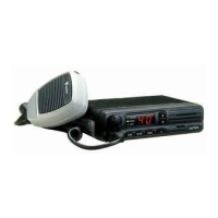
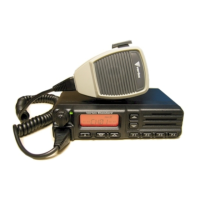
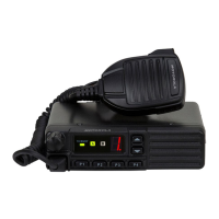
This manual provides technical information necessary for servicing the VX-2000U UHF Land Mobile transceiver.
The VX-2000U is carefully designed to allow the knowledgeable operator to make nearly all adjustments required for
various station conditions, modes and operator preferences simply from the controls on the panels, without opening the
case of the transceiver. The VX-2000U Operating Manual describes these adjustments, plus certain internal settings.
Servicing this equipment requires expertise in handling surface mount chip components. Attempts by non-qualified
persons to service this equipment may result in permanent damage not covered by warranty.
For the major circuit boards, each side of the board is identified by the type of the majority of components installed on
that side.
In most cases one side has only chip components, and the other has either a mixture of both chip and lead components
(trimmers, coils, electrolytic capacitors, packaged ICs, etc.), or lead components only.
While we believe the technical information in this manual is correct, Vertex Standard assumes no liability for damage
that may occur as a result of typographical or other errors that may be present. Your cooperation in pointing out any
inconsistencies in the technical information would be appreciated. Vertex Standard reserves the right to make changes in
this transceiver and the alignment procedures, in the interest of technological improvement, without notification of the
owners.
©2003 VERTEX STANDARD CO., LTD. E095490A
Service Manual
VX-2000U
UHF Land Mobile Transceiver
Operating Manual Reprint............................ 2
Specifications................................................... 7
Exploded View & Miscellaneous Parts....... 8
Block Diagram ................................................. 9
Interconnection Diagram............................. 13
Circuit Description ...................................... 15
Alignment....................................................... 19
Contents
Board Unit (
Schematics, Layouts & Parts
)
MAIN Unit............................................................... 23
DISPLAY-1 Unit ...................................................... 55
DISPLAY-2 Unit ...................................................... 59
VR Unit..................................................................... 63
MIC Unit .................................................................. 64
VERTEX STANDARD CO., LTD.
4-8-8 Nakameguro, Meguro-Ku, Tokyo 153-8644, Japan
VERTEX STANDARD
US Headquarters
10900 Walker Street, Cypress, CA 90630, U.S.A.
International Division
8350 N.W. 52nd Terrace, Suite 201, Miami, FL 33166, U.S.A.
YAESU EUROPE B.V.
P.O. Box 75525, 1118 ZN Schiphol, The Netherlands
YAESU UK LTD.
Unit 12, Sun Valley Business Park, Winnall Close
Winchester, Hampshire, SO23 0LB, U.K.
VERTEX STANDARD HK LTD.
Unit 5, 20/F., Seaview Centre, 139-141 Hoi Bun Road,
Kwun Tong, Kowloon, Hong Kong
40 channel version 4 channel version