21
Alignment
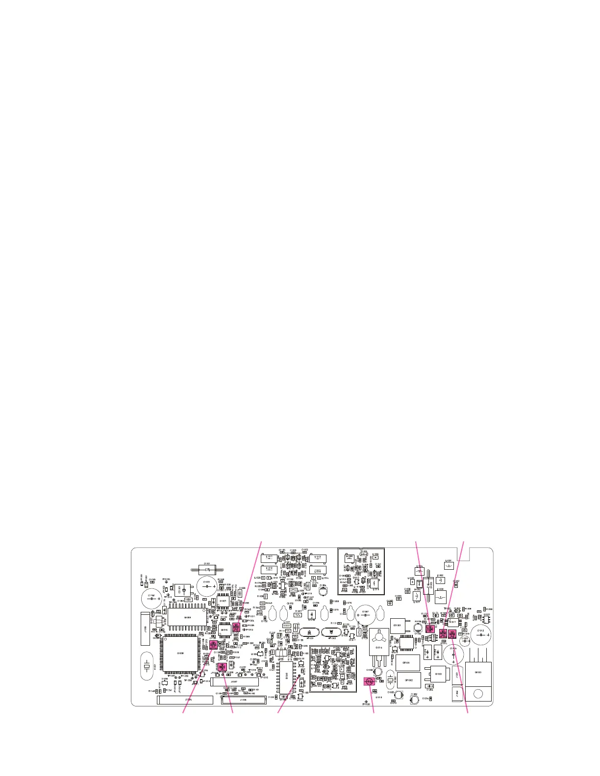
MAIN Unit Alignment Points
VR1001
VR1004 VR1005 TP1033 TC1001
VR1006 VR1002
VR1003
PLL VCV (Varactor Control Voltage)
Performance Check
r Connect the DC voltmeter between test point
TP1033 on the MAIN Unit and chassis ground.
r Set the transceiver to channel 3, and confirm
that the reading is about 4.5V (for Ver. A and
F) or 4.3V (for Ver. D).
r Now select channel 1, and confirm that the
reading changes to about 0.9V.
r Again select channel 3. Key the transmitter,
and confirm that the voltmeter reading is ap-
proximately 4.5V (for Ver. A and F) or 4.3V
(for Ver. D).
r Once more select channel 1 and again key the
transmitter. Confirm that the voltmeter read-
ing is approximately 1.0V.
PLL Reference Frequency
r With the wattmeter, dummy load, and fre-
quency counter connected to the antenna jack,
select channel 2.
r Key the transmitter, and adjust TC1001 on the
MAIN Unit, if necessary, so that the counter fre-
quency is within 200 Hz of 415.000.00 MHz for
Ver. A, 465.000.00 MHz for Ver. D or 496.000.00
MHz for Ver. F.
Transmitter Output Power
r Preset trimmer potentiometer VR1002 (MAIN
Unit) fully clockwise.
r Select (Band center) channel 2. Key the trans-
mitter, and confirm that at least 30 Watts of
power output is measured. Now select chan-
nels 1 and 3, and confirm that 30 Watts of RF
power is present on the band edge channels.
r Using the computer, re-program channel 1 for
“LOW” power output, and download this
data to the transceiver.
r Select channel 2, and adjust (“HIGH” power)
potentiometer VR1002 for 25 Watts of RF power.
r Select channel 1, and adjust “LOW” power) po-
tentiometer VR1003 for 5 Watts of RF power.
Transmitter Deviation
r Select channel 2, and adjust the AF genera-
tor’s attenuator so as to deliver 50 mV output
at 1 kHz to the microphone jack.
r Key the transmitter, and adjust VR1001 (MAIN
Unit) for ±4.3 kHz deviation as measured on
the deviation meter (tolerance: 100 Hz).
r On the computer, re-program channel 2 to en-
able a 100 Hz CTCSS (encode) tone, and down-
load this data to the transceiver.