Chapter 2 Installation 5
VERTIV
TM
GEIST
TM
Basic Rack PDU User Manual
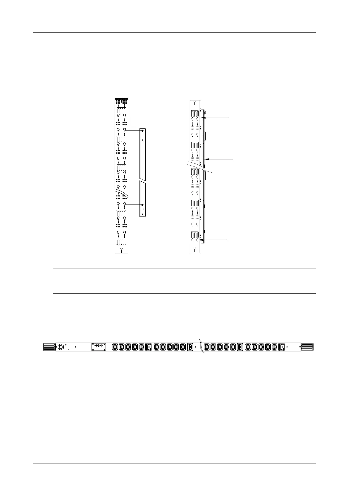
2) Press dow n the PDU until it is firmly clamped and locked, as shown in Figure 2-2.
3) Remove the PDU from the rack, lift the PDU vertically and make it slide upw ards until the button is out of the
mounting hole.
Figure 2-2 PDU Tool-less Installation
Note
The distance of the installation hole on the cable manager used for the tool-less installation should be an integral multiple of
312 mm.
2. Bracket Mounting
1) Install the brackets on both ends of the PDU w ith M3 × 10 Self tapping screw s, as show n in Figure 2-3.
2) Install the PDU on the rack w ith supplied accessory screw /nut, as show n in Figure 2-3.
Figure 2-3 Fixing the Bracket
Installed on the VE rack beam
Align the installation holes of the tw o 0U brackets with the higher row round hole of the top crossbeam and the
upper row round hole of the bottom crossbeam respectively and install the PDU on to the crossbeam of the VE
rack using four self-tapping screw s.