User Manual 10H52258UM60 - Rev. 3 - 01/2019
30
APM 400/600 Electrical Installation & Connections
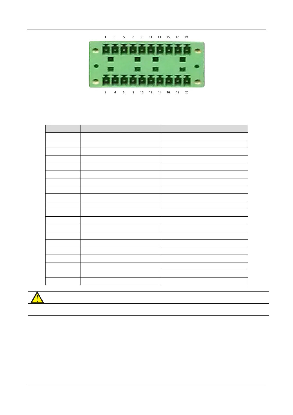
Figure 4-7 Dry Contact Port J22
See Table 4.5. for a pin-out description of Port J22
Table 4.5
Pin Name Description
1 12V_DRV BCB driver signal
2 NC Reserved
3 BCB STATUS BCB state signal
4 NC Reserved
5 GND_DRY Dry ground
6 NC Reserved
7 BCB_ONLine BCB on line signal
8 NC Reserved
9 NC Reserved
10 NC Reserved
11 GND_DRY Dry ground
12 NC Reserved
13 TMP_BAT External battery temperature
14 NC Reserved
15 12V_DRY Power
16 NC Reserved
17 GND_DRY Dry ground
18 NC Reserved
19 BAT_Ground_FAULT Battery ground fault
20 NC Reserved
Note
The BCB drive signal and external battery temperature signal
shielding sheath must be connected securely to the casing.