User Manual 10H52258UM60 - Rev. 3 - 01/2019
90
APM 400/600 Specifications
11.6
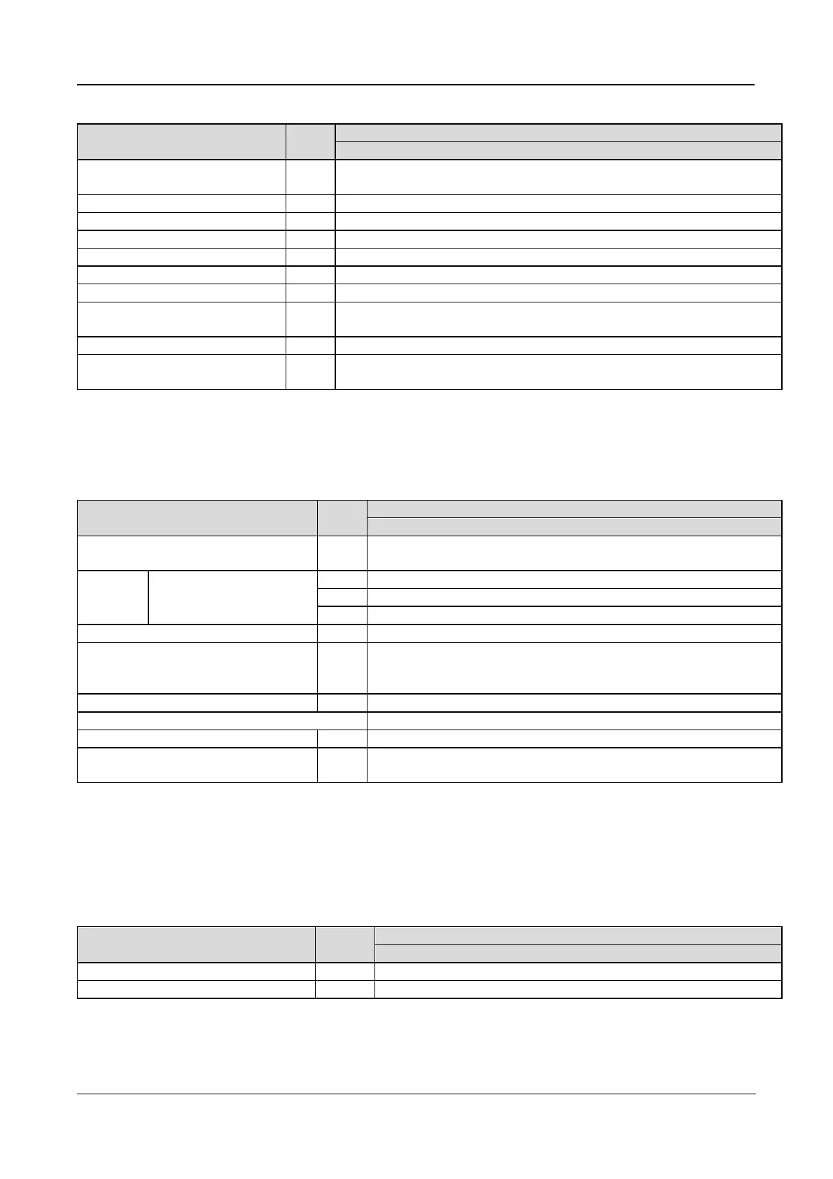
Electrical Specifications (Inverter Output)
Item Unit
Rated AC voltage
1
Vac
neutral)
2
≤1hr; <125, ≤10min; <150, ≤1min
3
Steady state voltage stability
±1 (balanced load), ±5 (100% unbalanced load)
Transient voltage response
distortion
% < 1 (linear load), < 3 (non-linear load)
Slew rate (max. change rate of
synchronization frequency)
Hz/s 0.6; setting range: 0.1 ~ 3
1. Factory set to 380V. 400V or 415V can be selected by service engineer at site.
2. Factory set to 50Hz. 60Hz can be selected by service engineer at site. Note that the system frequency can be
changed only when the UPS is on bypass. It is strictly prohibited to change the system frequency when the UPS
is on inverter.
11.7
Electrical Specifications (Bypass Input)
Item Unit
Rated AC voltage
1
Vac
wire, sharing neutral with the rectifier
input and providing neutral reference to the output
Rated
current
380V
400V
415V
2
Bypass voltage tolerance %Vac
Upper limit: +10, +15 or +20, default: +15
Lower limit: -10, -20, -30 or -40, default: -20
(bypass voltage normalization acceptance time: 10s)
Bypass frequency tolerance
commended External Bypass fuses
3
2
2
2
Projected short circuit current Icp
3 4
Minimum duration time for
short-circuit current
ms 60
1. Factory set to 380V. 400V or 415V can be selected by service engineer at site
2. Factory set to 50Hz. 60Hz can be selected by service engineer at site
3. External bypass fuses are mandatory for the declared short-circuit current protection value. Maximum
allowable value of projected short-circuit current at the input terminals of the fuses. If no external bypass fuses
are fitted, the short-circuit current value must be assumed to be 20kA
4. For additional information, contact Technical Support
11.8
Heat Losses
Item Unit
The above condition is applicable when the input and output voltage range is set to 400V and the battery is fully
charged




 To Next Page