Appendix 3 Wiring Diagram 29
NetSure 531 A41, NetSure 531 A91 Subrack Power system User Manual
MFU
8
M820B
7
1
2
3
4
5
6
7
8
9
10
11
12
13
14
15
16
17
18
19
20
21
22
23
24
25
26
27
28
29
30
31
32
33
34
35
36
37
38
39
40
41
42
43
44
45
46
47
48
49
50
24-CAN-
24-CAN+
13-J2-3
13-J2-4
13-J2-1
8-QFB1-1
8-QFB2-1
10-2
10-1
W80W80
W80
X3-2
W809-BUS+-2
X6-1 X5-1
8-B--1
W80
8-PL-1
W80
9-BUS+-1
W80
W80
8-PL-1
51
52
53
54
55
56
57
58
59
60
61
62
63
64
65
66
67
68
69
70
71
72
73
74
75
76
77
78
79
80
81
82
83
84
85
86
87
88
89
90
91
92
93
94
95
96
97
98
99
100
13-J2-2
X9
12-2
11-2
W80
W80
W80
W80
W80
J2
J11 J12
J3 J4 J5
J6 J7 J8 J9
13
IB2
1
2
4
3
11-1
W80
12-1
W80
W80
1
2
3
5-3
W07
2
1
1
2
PL
1
2
1
2
7-55
QFB1
QFB2
7-56
7-20
7-22
7-80
7-82
W80
8-B-
1
2
1
2
QFD5
QFD6
1
2
QFD7
1
2
QFD8
PL
0V
PE
5
1
BUS+
9
RB
10
KM2
12
2
9-2
1
W82+W81+W80
7-59
W80
W80
W80
W80
W80
7-35/7-47/7-49/7-50
7-44
7-31/7-46
NPL
1
2
1
2
QFD1
QFD2
1
2
1
2
QFD3
QFD4
NPL
7-59
1
7-79
W80
2
7-81
KM1
11
W80
Shelf 1
6
L1
1 3
2 4
N
QFA
1
4
2
3
W809-BUS+-1
W80
X5-1/X6-1
W82+W81+W80
W80
8-QFD
12
W07
8-PL
W01
W01
2
1
to M820 B
H5
DC-
DC-
L N L N
L N
L N
J2
J1
J4
J3
H2
H1
J13
J11
H3 H4
DC+
U1 U2
DC+DC-
J12 U3
DC+
U4
DC+DC-
J14
U11 U12 U13 U14
DC-
DC+
1-2
1-4
31
W2493ZX1
1-4
1-4
1-4
1-2
J41
CAN+
CAN-
J42
CAN+
CAN-
7-4
7-2
W02
W1 W1 W1 W1
X3-1
1-2
1-2
2
1
W02
31-J1-L
31-J2-L
31-J3-L
31-J4-L
31-J1-N
31-J2-N
31-J3-N
31-J4-N
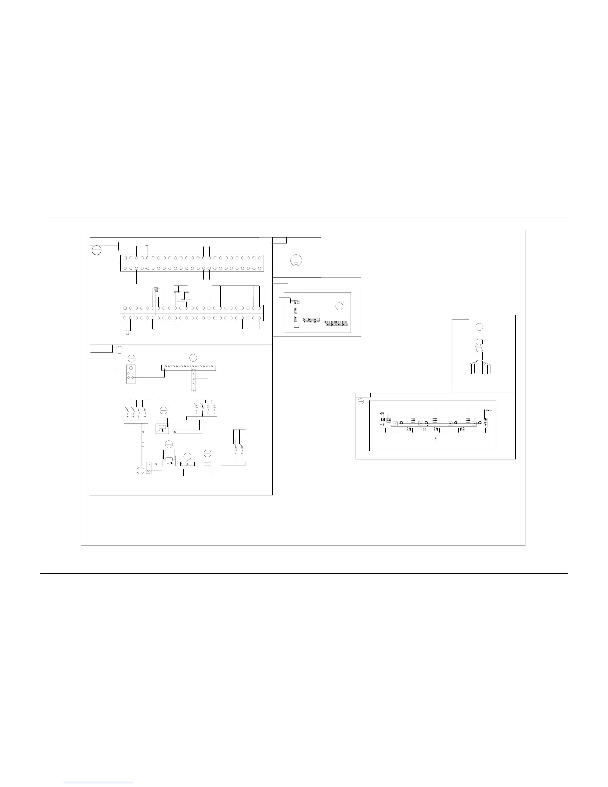
MFU DC wiring diagram
Rear top view
TO the protection earth of the users
To the positve busbar
TO the negative busbar
Subrack
Front top view of the back plat(with the contorller and rectifier)
Single-phase AC input
Front view
User interface
board 1
Front top view (open the panel)
Door connected
ground
Description
:
1. Connected the X3-1 to the X3-2, connected X3-1 to the X3-2.
2. Connected the X5-1 and the X6-1 to the cable of the
temperature sensor for system configuration.
Controller busbar socket
Front view

 Loading...


