Appendix 3 Wiring Diagram 30
NetSure 531 A41, NetSure 531 A91 Subrack Power system User Manual
B
MFU
8
1
2
3 5-3
W07
2 1
1
2
PL
Shelf 1
6
Top view
1
2
1
2
7-30
QFB1
QFB2
7-28
7-20
7-22
7-41
7-39
W80
8-B-
1
2
1
2
QFD1
QFD2
1
2
QFD3
1
2
QFD16
PL
0V
PE
5
M221S
7
1
BUS+
9
RB
10
KM2
12
2
9-2
1
W80+W81+W82
7-29
W80
W80
W80
W80
W80
W80
7-35/7-47/7-49/7-50
7-44
7-46
7-31
MFU door connected ground
DU
17
0V
DU distribution unit
Rear view
PL
8-QF17
8-QF18
1
2
1
2
W80+W81+W82
To the MFU unit PL bar
To the MFU positive extension bar
7-29
1
2
3
4
5
6
7
8
9
10
11
12
13
14
15
16
17
18
19
20
21
22
23
24
25
26
27
28
29
30
31
32
33
34
35
36
37
38
39
40
41
42
43
44
45
46
47
48
49
50
13-J8-1
24-CAN-
11-2
11-1
24-CAN+
13-J7-1
13-J7-2
13-J8-2
13-J8-3
13-J8-5
13-J8-4
13-J8-6
13-J8-7
13-J8-8
8-QFB2-1
8-QFB1-1
10-2
10-1
W80
W80
W80
W80
W80 W80
W80
X3-2
W809-BUS+-1
X6-1 X5-1
8-B--1
W80
8-PL-1
W80
9-BUS+-1
W80
W80
8-PL-1
W80
X7-2
W80
W809-BUS+-2
2
W80
X5-1/X6-1
Three-phase AC input
L2L1 L3
1
3 5 7
2
4 6 8
N
QFA
1
31-J1-L/31-J4-L/32-J2-L
W01 W01 W01
13
W2453X1
W2453X1
J6
21
J3
1+
1-
2+
2-
J8
1
8
W80
J7
1 2
J4
3+
3-
4+
4-
DO3
DO4
DO1
DO2
31-J1-N/31-J2-N/31-J3-N/31-J4-N
To the DU unit PL bar
4
8-QFD
DU door connected ground
1 2
3
2
1
to M 221 S/M 222S
H5
DC-
DC-
L N L N
L N
L N
J2
J1
J4J3
H2
H1
J13
J11
H3 H 4
DC+
U1 U 2 DC +DC-J12 U3
DC+
U4
DC+DC -
J14
U11 U12 U13 U1 4
DC-
DC+
1-2
1-8
31
W24 93Z X1
1-8
1-4
1-8
1-6
1-8
1-2
W02
J41
CAN +
CAN -
J42
CAN +
CAN -
7-4
7-2
W02
W1 W1 W1 W1
H5
DC-
DC-
L N L N
L N
L N
J2
J1 J4J3
H6
H1
J13
J11
H3 H4
DC-J12
DC-
J14
U11 U13 U14 U1 5
DC-
DC+
1-6
1-8
32
W249 3Z X2
1-8
1-2
1-8
1-4
1-8
1-6
W02
J41
CAN+
CAN-
J42
CAN+
CAN-
W1 W1 W1 W1
H2
U12
DC-
J15 DC +J25
L N
J5
1-4
1-8
W1
2
1
W02
DC+J2 1 D C+J2 2 DC+J2 3 DC+J 24
22-J 41-1
22-J 41-2
31-J4 1-1
31-J41 -2
31-J2-L/32-J5-L/32-J3-L
31-J3-L/32-J1-L/32-J4-L
32-J1-N/32-J2-N/32-J3-N/32-J4-N/32-J5-N
W01 W01
X3-1
8-PL
W07
W07
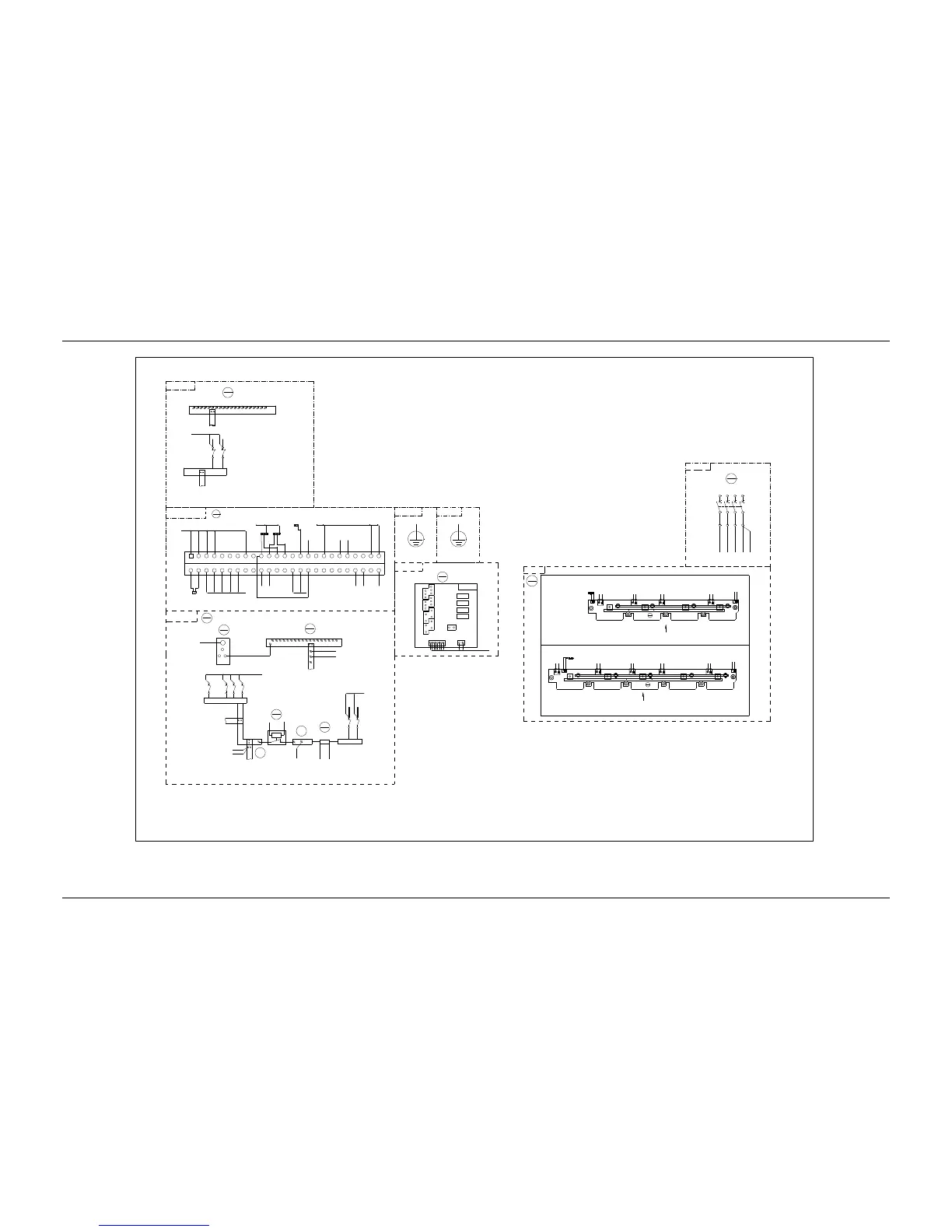
Front top view Back plant of the rectifier in the subrack
Controller busbar socket
Front view
MFU DC wiring diagram
Rear top view
TO the protection earth of the users
To the positve busbar
TO the negative busbar
Subrack
Front top view of the back plat(with the contorller and rectifier)
User interface
board 1
Front top view (open the panel)
Description
:
1. Connected the X3-1 to the X3-2, connected X3-1 to the X3-2.
2. Connected the X5-1 and the X6 -1 to the cable of the
temperature sensor for system c onfiguration.

 Loading...


