Vertiv | NetSure 7100 Series Quick Start Guide (QS582127000) | Rev. T
MAKE JUMPER AND SWITCH SETTINGS
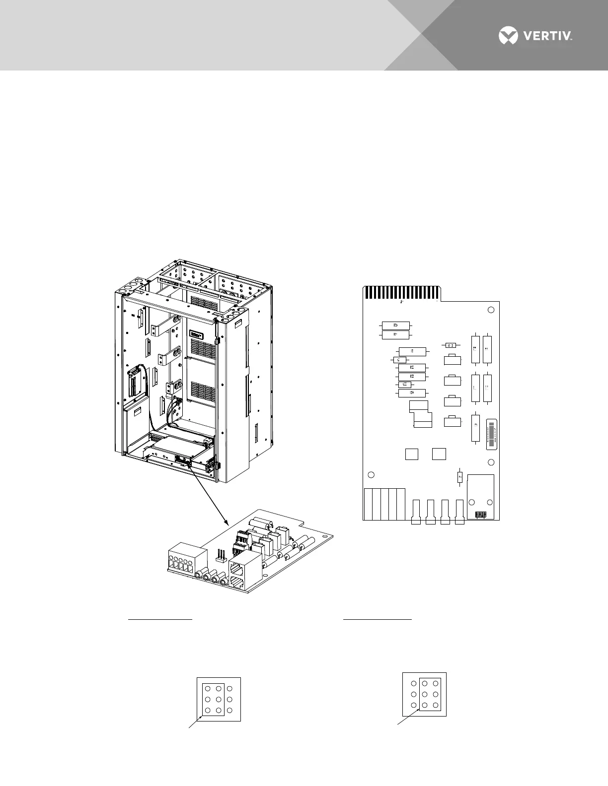
Various circuit cards installed in the system have switch and jumper settings.
Switch Settings: All switch settings set the various circuit cards to operate properly with this system and have
been factory set.
Jumper Settings: The jumpers located on the system interface circuit card are customer selectable. Refer to
Figure 8 for jumper locations and function. Refer to SETTING JUMPERS AND SWITCH OPTIONS in the
Installation Instructions (IM582127000) for a complete procedure.
Figure 8:
System Interface Circuit Card Jumper Locations
1
1A 2A 3A
1B 2B 3B
5
J1
J2
J3
J4
J8
TB2
TB1
TP1 TP2 TP3 TP4
J10
J5
TB1-2, TB1-3, TB1-4, TB1-5 Main Bay Only.
TB1-4: External Battery Monitoring (-)
TB1-5: External Battery Monitoring (+)
4-Row Cabinet Shown,
Others Similar
(Front Door Removed in
Illustration for Clarity)
System Interface
Circuit Card
System Interface
Circuit Card
External Internal
J10
1
2
3
7
8
9
J10 (Main Bay Only)
Battery Monitoring External / Internal
(see TB1-4 and TB1-5 for
external monitoring points)
Shorting Jumper
J8 (Main Bay Only)
Selects to power Controller
from “Battery Power” or not.
No
Battery
Pwr
Battery
Pwr
J8
1
2
3
7
8
9
Shorting Jumper

 Loading...


