These installation instructions provide essential information for installing VESDA-E VEA Aspirating Smoke Detectors in accordance with the system design. Additional installation and
product documentation is listed below in the Reference Documents section.
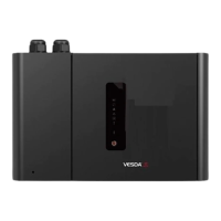
VESDA-E VEA Installation Instructions
System Components
The detector is shipped with the following components:
• 1 aspirating smoke detector
• 1 mounting bracket
• 1 mounting template for directly mounting the detector to the mounting surface
• 1 End of Line Resistor for the monitored GPI
• 1 installation instruction sheet
• 40 tube inlet blanking plugs (P/N VSP-998)
Prerequisites
• A completed system design.
• A 24V DC Power Supply and backup battery, compliant with local codes and
standards.
• Screws and inserts that are appropriate for the installation location.
• Type A to Type B USB Interface Lead, required for initial conguration of the
detector.
• Labels as specied in the system design, e.g. Sampling Point labels
• Cable glands that are compliant with the IP rating of the detector.
• Conduit, as specied in the system design.
• 1.1 mm
2
(18 AWG) or larger wiring for power.
• 0.2 mm
2
to 2.5 mm
2
(24 - 12 AWG) wiring for relays.
• A PC or laptop installed with Xtralis VSC for initial conguration.
• Standard connection instructions for where the detectors are to be added to a corporate
network.
Standards Compliance
UL and ULC
• Special Application: High (1.6%/m [0.5%/ft]) to Standard (8.0%/m [2.5 %/ft])
• Open Area Protection, 0 to 300 ft/min air velocity: High (1.6%/m [0.5%/ft]) to
Standard (8.0%/m [2.5%/ft])
• Open Area Protection, 300/1000/2000 ft/min air velocity: High (1.6%/m [0.5%/ft]) to
Enhanced (4.0%/m [1.3%/ft])
• Open Area Protection, 3000/4000 ft/min air velocity: High (1.6%/m [0.5%/ft])
Power Consumption (24 VDC Supply)
Model Average
Quiescent
Average
Alarm
Peak
Current
VEA-040-A00 22 W 35.5 W 3.5 A
VEA-040-A10 23 W 36.5 W 3.5 A
Environmental Requirements
• Temperature
• Ambient: 0°C to 39°C (32°F to 102°F)
• Sampled Air: 0°C to 50°C (32°F to 122°F)
• Tested to: 0°C to 49°C (32°F to 120°F)
• Humidity: 10-95% RH, non-condensing
Note:
Please consult your Xtralis representative for information on operation outside
these parameters or where sampled air is continually above 0.05% obs/m
(0.015% obs/ft) under normal operating conditions.
Transport Time
Transport time is determined by the length of the microbore tubes used on the detector.
There is no provision for the user to adjust the transport time and there is no tube
modelling tool required for VEA.
The transport time is given in the table below for various tube lengths.
Maximum Tube Length Longest Transport Time
30m [98ft] 40 seconds
40m [131ft] 46 seconds
50m [164ft] 53 seconds
60m [197ft] 60 seconds
70m [230ft] 67 seconds
80m [262ft] 74 seconds
90m [295ft] 82 seconds
100m [328ft] 90 seconds
Reference Documents
Additional installation and product information is contained in the following documents,
which are available for download in the Xtralis partner extranet at www.xtralis.com.
• 27034 - VESDA-E VEA-040-A00 Product Guide
• 27035 - VESDA-E VEA-040-A10 Product Guide
Installation Instructions
The detector must be mounted vertically to a solid surface.
Attach the detector using the mounting bracket
Position electrical conduit, mark pilot holes
B
A
D
D
D
D
D
• Position the mounting bracket (A) to allow
electrical conduit (B) to line up horizontally with
the alignment marks (C).
• Mark positions for pilot holes on the mounting
surface through ve recessed screw holes
(D).
• Remove the mouting plate and drill pilot
holes.
Secure Mounting Bracket
E
E
E
• Reposition the mounting bracket and secure to
mounting surface by screwing the ve screws (E)
into their pilot holes.
Attach the detector to the mounting bracket
F
F
F
F
• Align the four mounting studs (F) on the rear of
the detector with the mounting stud slots on the
mounting bracket, and slide the detector down
until the top of the detector is ush with the top of
the mounting bracket.
Secure the detector to the mounting bracket
G
• Open the door by inserting an Allen key
(preferred), Philips head screwdriver or at blade
screwdriver with the blade vertically oriented into
the hole at bottom left and press rmly.
• Insert and tighten the locking screw (G). This
secures the detector to the mounting bracket.
• Insert the electrical conduit.
Attach the detector directly to the mounting surface
Use the provided mounting template. Refer to the product guide for further informa-
tion.
Prepare Detector: Wiring Inlets
Remove the appropriate plugs for electrical cable installation.
• Do not remove the plugs from holes that will not be used.
• Feed the electrical wiring connections through the cable entry ports.
• Use the correct cable gland size to t into the 26 mm (1”) cable entry port. Use
correctly rated cable glands to maintain the required IP rating.
Note: To remove the cable entry port plugs,
place a large screwdriver in the
large slot and twist, or use a small
screwdriver in the side slots to lever
the plug out.
www.acornfiresecurity.com
www.acornfiresecurity.com