I.
ELECTRICAL
CONTINUED
P200E(VSX1
T)
ELECTRONIC IGNITION SYSTEM
(DUCATIIGNITION)
Continued
The flywheel generates on
ignition
coil
(B),
and alternating current that when
rectified
by the
diode
(02) charges the condenser
(C1).
The pick-up
unit
(P)
supplies
immediately
the
control
signal
to
the
thyristor
(SCR);
Thyristor
(SCR)
feeds the discharge
of
condenser
(C1)
on the high
tension
coil
(primary side) and hence produces on the secondary coil the necessary voltage
for
the spark plug.
P200E(VSX1 T) STATOR PLATE TESTING
(DUCATIIGNITION)
If in case
of
a suspected defective
ignition
system, the
following
action
must
be taken in
the
appropriate steps
as
listed below.
Step
#1.
Step#2.
Step#3.
Visually
inspect
ALL
ignition
related
terminals
and
wiring
for
possible
breaks
and improper connections.
Verify engine cut-off
switch
(@
Fig.
3)
is in
OFF
position.
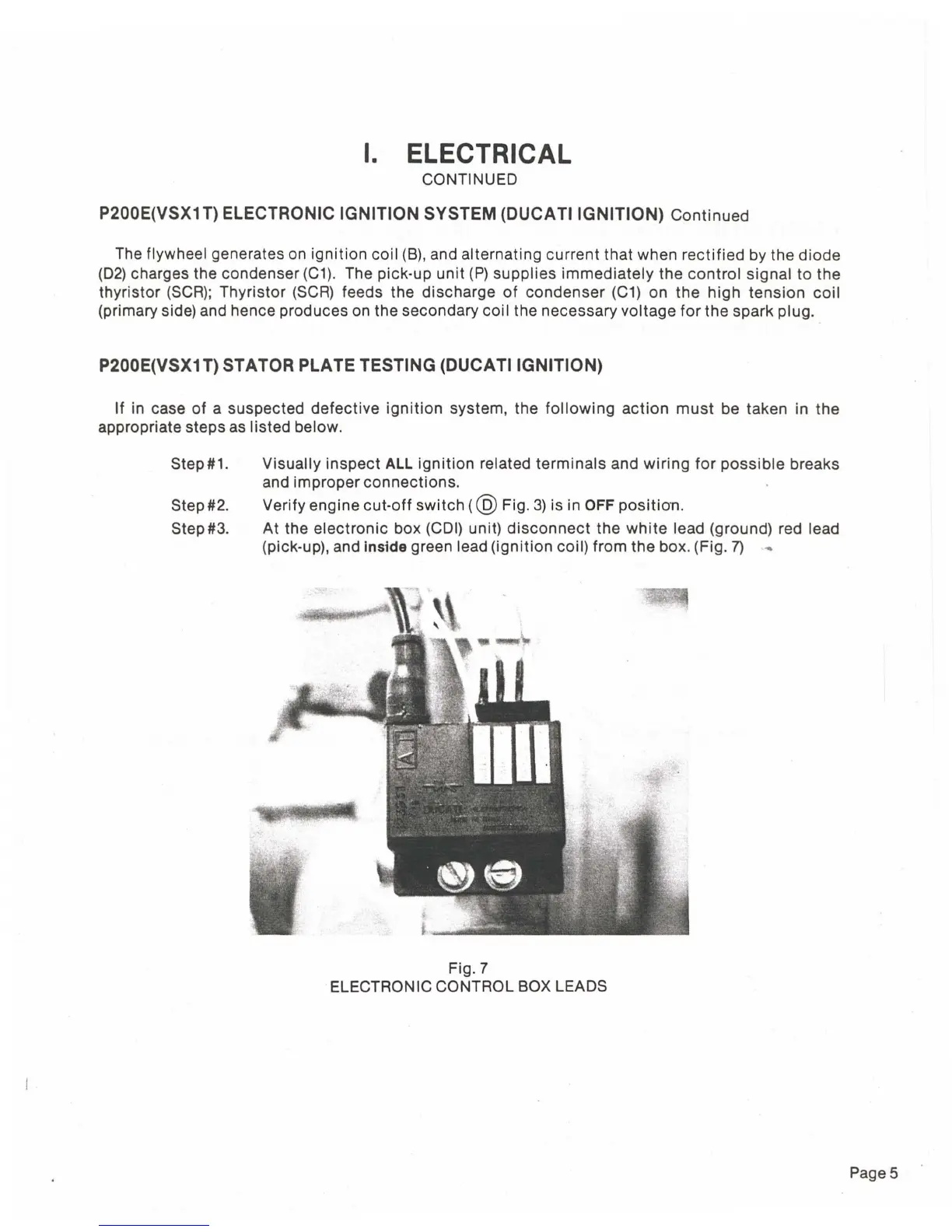
At the
electronic
box (COl) unit)
disconnect
the
white
lead (ground) red lead
(pick-up), and
inside green lead
(ignition
coil) from the box. (Fig.
7)
Fig.7
ELECTRONIC CONTROL BOX LEADS
Page 5
 Loading...