Do you have a question about the VEVOR PM8225D and is the answer not in the manual?
Provides contact details for technical support and warranty services.
Covers copyright, manual usage, and a summary of the instrument's capabilities.
Details essential safety instructions, warnings, and explains important safety symbols.
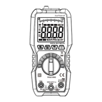
Identifies and describes the multimeter's LCD display, keys, input jacks, and sensing areas.
Explains the meaning of various indicators and symbols displayed on the multimeter's screen.
Guides through precautions and steps for AC voltage and mV gear voltage measurements.
Covers resistance, connectivity, diode, capacitance, and temperature measurements.
Details Non-Contact Voltage (NCV) and Live wire detection methods.
Explains procedures for frequency, duty ratio, uA, and mA current measurements with warnings.
Outlines the procedure for measuring A current, along with important safety warnings.
Lists detailed accuracy indices for AC voltage, DC voltage, resistance, and capacitance.
Includes specifications for frequency, duty ratio, AC/DC current, and temperature.
Provides instructions for general maintenance, cleaning, and replacing batteries.
Details crucial warnings regarding correct fuse tube specification and parameter usage.
This document is a user manual for the VEVOR PM8225D Multimeter, a compact, hand-held digital multimeter designed for high performance and reliability. It features a 6000-count display and is equipped with an overload protection circuit, making it suitable for a variety of electrical measurements.
The VEVOR PM8225D Multimeter is capable of measuring both AC and DC voltage and current, resistance, diode, circuit connectivity, non-contact electricity verification (NCV), and live wire detection. A notable feature for AC voltage measurement is the integrated VFD low-pass filter, which allows for accurate measurement of inverter voltage with a filter attenuation of -0.94dB at 1kHz.
The device's main display is a 4-digit, 7-segment nixie tube, providing 6000 counts, complemented by an analog bar indication for quick visual reference. The multimeter includes several key functions accessible via dedicated buttons and a rotary switch.
For voltage measurements, the device supports both AC and DC voltage, including a specific mV gear for smaller voltage readings. Users can switch between DC voltage, AC voltage, frequency, and duty ratio using the "SEL VFD" key. The VFD low-pass filter, specifically for AC voltage, can be toggled on or off by long-pressing the "SEL VFD" key.
Resistance, connectivity, diode, and capacitance measurements are grouped under a single rotary switch position. The "SEL VFD" key allows switching between these functions. For connectivity tests, the device indicates conductive resistance less than 30 Ω with a continuous buzzer sound. Diode measurements display the approximate forward voltage value.
Temperature measurement is also supported, with a dedicated "Temp" position on the rotary switch. Users can insert a thermocouple into the designated jacks and read the temperature in either Celsius or Fahrenheit by pressing the "SEL VFD" key.
The multimeter features non-contact electricity verification (NCV) and live wire detection (Live) functions. In NCV mode, placing the sensing area near a wire detects AC voltage, triggering an intermittent buzzer sound and displaying a varying number of bars on the screen, indicating the intensity of the induced voltage. The Live function, used with the red probe connected to the cable, detects AC voltage greater than approximately 36V, also indicated by an intermittent buzzer and varying bar display. The NCV mode offers higher sensitivity for live wire detection compared to the Live mode.
Current measurements are available for microamperes (uA), milliamperes (mA), and amperes (A), supporting both AC and DC currents. Each current range has dedicated input jacks (600mA and 10A) and allows for frequency measurement within these modes by using the "SEL VFD" key. The device displays the polarity of the red probe connection when current values are shown.
Additional features include a "MAX MIN" key for starting maximum or minimum value measurements, a "REL" key for relative value measurements and lighting control, and a "HOLD" key for data retention and LCD backlight control. The device also has an automatic shutdown function after about 10 minutes of inactivity, indicated by a specific symbol on the display. This function can be disabled by a specific key press sequence during startup. The backlight and lighting functions also turn off automatically after about 15 seconds.
Before operation, users are instructed to check the battery voltage, indicated by a battery symbol on the screen. If the symbol appears, the battery needs replacement. The manual emphasizes the importance of not exceeding the indicated input voltage or current values to prevent damage to the internal circuit.
When measuring, it is crucial to use the correct function and range gear. The device displays "OL" when the range is exceeded, indicating that the measurement should be terminated or a higher range selected. Users are warned against inputting voltages higher than 600V AC or DC, as this poses a risk of damaging the instrument. Special attention is advised to avoid electric shock when measuring high voltage.
For capacitance measurements, large capacitances should be discharged before testing. When using the NCV/Live functions, users are reminded that even without sound or display prompts, a wire might still have voltage, as external factors like shielded wires or insulation thickness can affect detection. It is strictly forbidden to insert fingers or conductors into the COM jack during live wire judgment to prevent electric shock.
The manual provides clear instructions for connecting probes: the red probe for positive input and the black probe for the common input (COM). For current measurements, the probes must be connected in series with the load. When disconnecting, the live wire should be cut off first, followed by the neutral and ground wires. Users are advised to hold fingers behind the probe finger protector for safety.
The manual outlines basic maintenance procedures, including battery and fuse tube replacement. It strongly warns against using the instrument for any measurement operation when the shell is opened to prevent electric shock, fire, or physical injury. Before cleaning, all input signals must be removed.
Regular cleaning of the instrument shell with a wet cloth and a small amount of detergent is recommended, avoiding abrasive or chemical solvents.
Battery replacement is necessary when the low battery indicator appears on the display. To ensure safe operation and prevent damage from battery leakage, the battery should be removed if the instrument is not used for an extended period. The process involves turning off the instrument, disconnecting probes, loosening screws on the battery cover, replacing the two DC 1.5V AAA batteries, and reassembling.
Fuse tube replacement also requires turning off the instrument, disconnecting probes, and removing the protective leather case. The manual specifies the correct fuse specifications: 600mA/250V for the 600mA jack and 10A/250V for the 10A jack. It is strictly forbidden to use fuse tubes with different specifications to avoid damaging the instrument. All repairs should be performed by an approved technician using designated replacement parts.
| Display Type | LCD |
|---|---|
| Max Voltage (DC) | 1000V |
| Max Voltage (AC) | 750V |
| Max Current (DC) | 10A |
| Max Current (AC) | 10A |
| Data Hold | Yes |
| Backlight | Yes |
| Diode Test | Yes |
| Continuity Test | Yes |
| Battery | 9V |
| Safety Rating | CAT III 600V, CAT II 1000V |
| Resistance Measurement | 40MΩ |
| Frequency Measurement | 10MHz |
| Temperature Range | -20℃ to 1000℃ |