12
Permissible thrust load [Unit: N (lb.)]
The box (∗
1
) represents the desired gear ratio (3.6, 7.2, 10, 20, 30, 50).
The box (∗
2
) represents the desired gear ratio (50, 100).
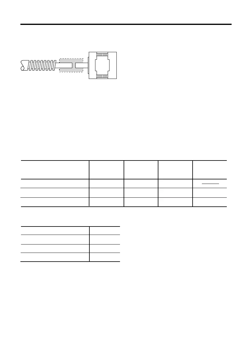
Connecting the motor to the drive mechanism (Load)
Proper alignment is necessary when
connecting the drive mechanism (load) to
the motor shaft. Use a flexible coupling.
Distance from the end
of the shaft [mm (inch)]
PMC3
A(B)3
PMC33A(B)1-MG
∗
1
PMC33A(B)1-HG
∗
2
0
25 (5.51)
9.2 (2.02)
140 (30.8)
15 (0.59)
21.9 (4.82)
240 (52.8)
5 (0.2)
34 (7.49)
11.4 (2.51)
160 (35.2)
10 (0.39)
52 (11.4)
15 (3.3)
200 (44.1)
Note
• Inadequate alignment may reduce the life span of the motor bearings or damage the
motor shaft.
• Exceeding the permissible overhung load or permissible thrust load will damage or shorten
the life span of the bearings and motor shaft.
Do not exceed the permissible overhung load and thrust load as indicated in the
following chart.
• For geared motor, do not separate the motor and the gearhead.
Permissible overhung load [Unit: N (lb.)]
Ball screw
Coupling
Stepping motor
PMC33A(B)3
PMC35A(B)3
PMC33A(B)1-MG
∗
1
PMC33A(B)1-HG
∗
2
1 (0.22)
1.7 (0.374)
10 (2.2)
100 (22)