15
Pulse input mode switch (Factory setting : 1P)
Select the appropriate pulse input mode to correspond to
your controller with this switch.
When the switch is set to the 1P position, 1-pulse input
mode is established and motor rotation is controlled by
pulse signals and rotation direction signals.
When the pulse input mode switch is set to the 2P position,
2-pulse input mode is established and motor rotation is
controlled by CW and CCW pulse signals.
When the switch is set to:
“F” (Full step)
Standard type: 1step = 0.72° (1 rotation = 500 pulses)
Geared type: 1step= 0.72°×
(1 rotation = 500×gear ratio pulses)
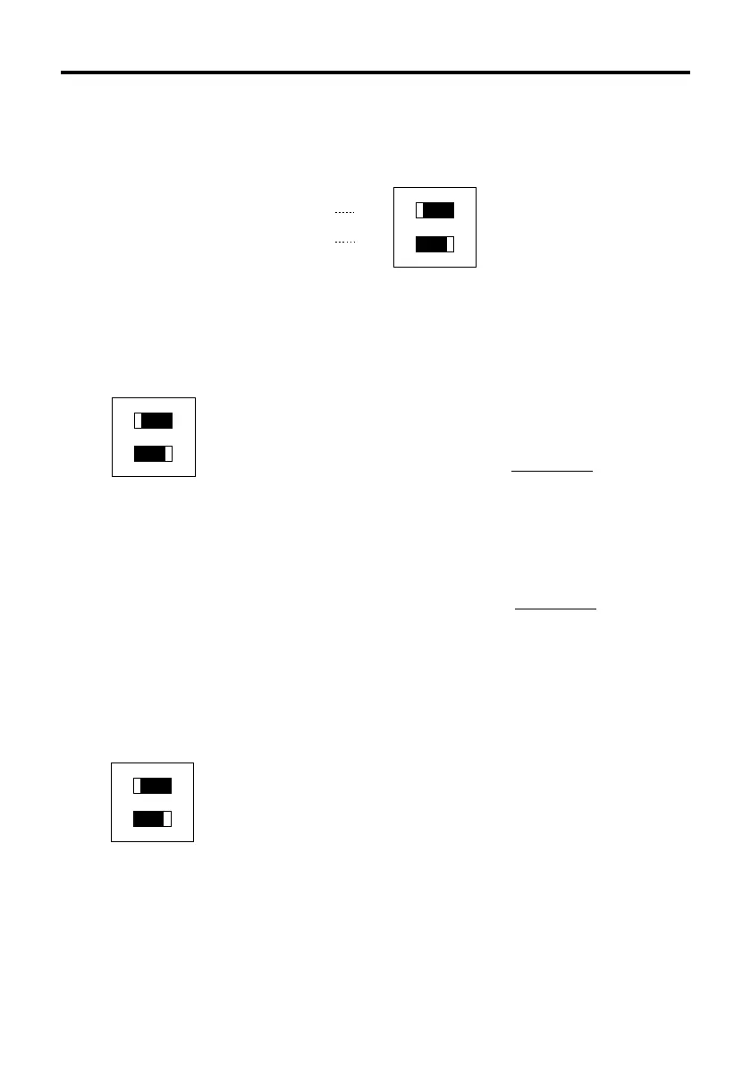
Driver function switches
The driver has various operation functions which are set with the function switches.
F
H
2P
1P
OFF
ON
ON
12
Step angle switch
Pulse input mode switch
∗The white square section of the function switch represents the switch lever.
Step angle switch (Factory setting : F)
2P
1P
ON
12
F
H
ON
1
2
“H” (Half step)
Standard type: 1step = 0.36° (1 rotation = 1000 pulses)
Geared type: 1step = 0.36°×
(1 rotation =1000×gear ratio pulses)
1
gear ratio
1
gear ratio