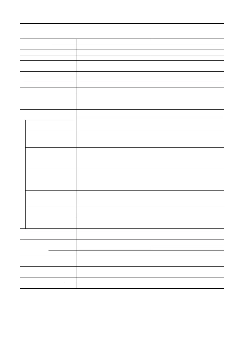
30
Specifications
• Maximum holding torque refers to the holding torque at motor standstill when the rated current is supplied to the
motor (5-phase excitation). Use this value to compare motor torque performance. When using the motor with the
included driver, the driver’s “Automatic Current Cutback” function at motor standstill reduces maximum holding
torque by approximately 50%.
• The power source input current value represents the maximum current. (The input current varies according to the
pulse frequency.)
Note
•
Do not measure insulation resistance or perform the dielectric withstand test while the motor and driver are connected.
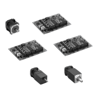
PMC33A3
PMC33B3
0.033 (4.58)
9×10
-7
(0.05)
PMC35A3
PMC35B3
0.06 (8.33)
18×10
-7
(0.099)
Package Model
Single Shaft
Double Shaft
Maximum Holding Torque
Rotor Inertia
Rated Current
Basic Step Angle
Shaft Runout
Perpendicularity
Concentrictly
Insulation Class
Power Source
Output Current
Excitation Mode
N·m (oz-in)
kg·m
2
(oz-in
2
)
A/phase
mm (inch)
mm (inch)
mm (inch)
0.35
0.72°
0.05 (0.002) T.I.R. at top of output shaft
0.075 (0.003) T.I.R.
0.075 (0.003) T.I.R.
Class B [130°C (266°F)]
DC24V±10% 0.7A or
DC36V±10% 0.7A
0.35
•Full step (4 phase excitation): 0.72°/step
•Half step (4-5 phase excitation): 0.36°/step
Photocoupler input, Input resistance 220Ω, Input current 20mA maximum
Signal voltage Photocoupler ON: +4~+5V, Photocoupler OFF: 0~+0.5V
Step command pulse signal (CW step command signal at 2-pulse input mode)
Pulse width: 5µs minimum, Pulse rise/fall: 2µs maximum
Motor moves when the photocoupler state changes from ON to OFF.
Rotation direction signal Photocoupler ON: CW, Photocoupler OFF: CCW
(CCW step command signal at 2-pulse input mode
Pulse width: 5µs minimum, Pulse rise/fall: 2µs maximum
Motor moves when the photocoupler state changes from ON to OFF.)
Full Step (0.72°) at “photocoupler OFF”
Half Step (0.36°) at “photocoupler ON”
When in the “photocoupler ON” state, the current to the motor is cut off and the motor shaft can be rotated manually.
When in the “photocoupler OFF” state, the current level set by the RUN switch is supplied to the motor.
When in the “photocoupler ON” state, the “Automatic Current Cutback” function at motor standstill is disabled.
When in the “photocoupler OFF” state, the “Automatic Current Cutback” function at motor standstill is activated.
(approximately 100ms after motor stops)
Photocoupler, Open-Collector Output
External use condition : 24VDC maximum, 10mA maximum
Signal is output every time the excitation sequence returns to the initial “0”. (Photocoupler: ON)
Full step: Signal is output every 10 pulses, Half step: Signal is output every 20 pulses
Automatic current cutback, All windings off, Pulse input mode switch
Power Input
Natural Ventilation
0.1 (0.22) 0.17 (0.38)
0.025 (0.06)
100MΩ minimum under normal temperature and humidity, when measured by a
DC500V megger between the motor coils and the motor casing.
Sufficient to withstand 0.5kV, 60Hz applied between the motor coils and
casing for one minute, under normal temperature and humidity.
-10°C~+50°C (+14°F~+122°F)
0°C~+40°C (+32°F~+104°F)
Input Signal
• Pulse Signal
(CW Pulse Signal)
• Rotation Direction Signal
(CCW Pulse Signal)
• Step Angle Signal
• All Windings Off Signal
•
Automatic Current Cutback
Release Signal
Output Signal Circuit
• Excitation Timing Signal
Functions
Indication (LED)
Driver Cooling Method
Mass
Insulation Resistance
Dielectric Strength
Ambient Temperature Range
Input Signals
Output Signals
Motor kg (lb.)
Driver kg (lb.)
Motor
Driver
 Loading...