7
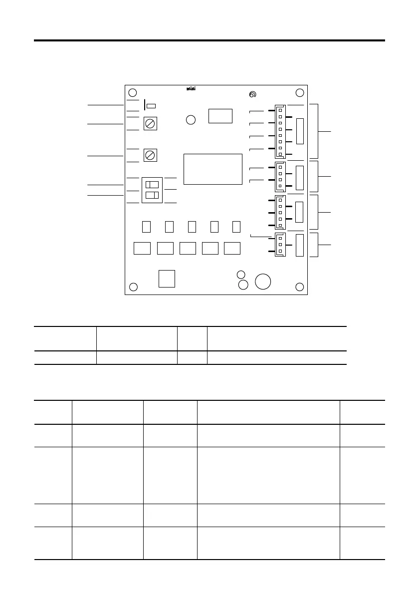
Names and functions of driver parts
Illustration shows the view from the connector side.
LED indications
GND
POWER
RUN
STOP
F
H
2P
1P
+
+
+
+
+
+
+
ORG
RED
TIM
BLU
GRN
BLK
24 / 36V
NC
SIGNAL 1
SIGNAL 2
MOTOR
POWER
1
1
1
CN1CN4CN3
1
CN2
C.UP
F/H
C.OFF
CCW/D.
CW/P.
VEXTA
STEPPING DRIVER
⑦
①
⑨
⑧
②
③
④
⑤
⑥
Potentiometers and switches
Indication
② RUN
③ STOP
④ F/H
⑤ 2P/1P
Run potentiometer
Stop potentiometer
Step angle switch
Pulse input mode
switch
0.35A/phase
0.175A/phase
F
1P
Name
Factory
setting
Current adjustment potentiometer used
when motor is running.
Motor standstill current adjustment
potentiometer used when current has
been cut back by the automatic current
cutback function when there is no pulse
input (motor standstill).
The motor step angle can be set to full
step or half step with this switch.
The pulse signal input mode can be set
to 1-pulse input mode or 2-pulse input
mode this switch.
Function
Page25
Page25, 26
Page15
Page15
Page
reference
Indication
① POWER Power input LED Green
LED name
Color
Lights when the power is input.
Conditions when LED ON