8
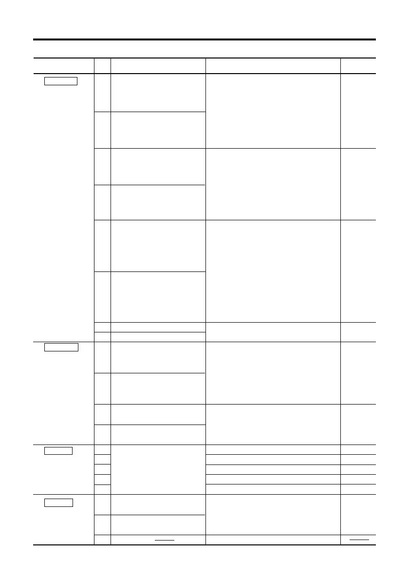
Terminals
Indication Terminal name Function
Pin
No.
Page
reference
Page16, 17
Page16, 17
Page18, 19
Page19
Page20
Page21
Page22, 23
Page22, 23
Page22, 23
Page22, 23
Page22, 23
Page22
The pulse mode signal is input to this
terminal. The direction of the motor’s
rotation is determined by the following
rotation direction input terminal.
(When in 2-pulse input mode the CW
direction command pulse signal is input
to this terminal.)
The rotation direction signal is input to
this terminal. When a signal is input to
the terminal the motor output shaft will
rotate the counterclockwise direction.
(When in 2-pulse input mode the CCW
direction command pulse signal is input
to this terminal.)
The all windings off signal is input to this
terminal.
When a signal is input to the terminal the
driver will cut the power supply to the
motor.
The motor torque will then be reduced to
zero and the motor shaft can be rotated
freely for adjustment.
This function is used when manual
positioning etc. is required.
The motor step angle is input to this
terminal.
The automatic current cutback release
signal is input to this terminal.
Signal for deactivating the automatic
current cutback function, which cuts back
the output current to the motor when it is
standstill.
Signal indicating that the motor excitation
sequence is at step “0”.
Connect this terminal to the blue lead wire.
Connect this terminal to the red lead wire.
Connect this terminal to the orange lead wire.
Connect this terminal to the green lead wire.
Connect this terminal to the black lead wire.
Connect this terminal to a “+” side of
DC24V or DC36V and GND.
No connection.
⑥ SIGNAL 1
6-173977-8
(AMP)
∗1
The selection of
the pulse signal
input mode can
be set with the
pulse input
mode switch.
∗2
In this table, the
rotation direction
shows that of
motor output
shaft.
For harmonic
geared type and
gear ratio 10:1 of
MG geared type,
the motor rotation
direction is
opposite to the
output shaft
rotation direction.
⑦ SIGNAL 2
6-173977-4
(AMP)
⑧ MOTOR
6-173977-5
(AMP)
⑨ POWER
6-173977-3
(AMP)
1
2
3
4
5
6
7
8
1
2
3
4
1
2
3
4
5
1
2
3
(Pulse/CW Pulse
Signal Input
Terminal)
(Pulse/CW Pulse
Signal Input
Terminal)
(Rotation Direction/
CCW Pulse Signal
Input Terminal)
(Rotation Direction/
CCW Pulse Signal
Input Terminal)
(All Windings Off
Signal Input
Terminal)
(All Windings Off
Signal Input
Terminal)
Motor Connection Terminal
24/36V
GND
NC
(Step Angle Signal Input Terminal)
(Step Angle Signal Input Terminal)
(Automatic Current
Cutback Release
Signal Input Terminal)
(Automatic Current
Cutback Release
Signal Input Terminal)
(Excitation Timing
Signal Output Terminal)
(Excitation Timing
Signal Output Terminal)
(Power Supply
Connection Terminal)
(Power Supply
Connection Terminal)
CW/P.+
CW/P.
-
CCW/D.+
CCW/D.
-
C.OFF+
C.OFF
-
F/H+
F/H
-
C.UP+
C.UP
-
TIM+
TIM
-