16
1-Pulse input mode
Pulse signal
When the photocoupler state changes from “ON” to “OFF”, the motor rotates one step.
The direction of rotation is determined by the following rotation direction signals.
Rotation direction signal
The rotation direction signal is input to rotation direction/CCW pulse signal input terminal.
An input signal at “photocoupler ON” commands a clockwise direction rotation.
(For harmonic geared type and gear ratio 10:1 of MG geared type: counterclockwise)
An input signal at “photocoupler OFF” commands a counterclockwise direction rotation.
(For harmonic geared type and gear ratio 10:1 of MG geared type: clockwise)
2-Pulse input mode
CW∗ pulse signal
When the photocoupler state changes from “ON” to “OFF”, the motor rotates one step in
the clockwise direction.
(For harmonic geared type and gear ratio 10:1 of MG geared type: counterclockwise)
CCW∗ pulse signal
When the photocoupler state changes from “ON” to “OFF”, the motor rotates one step in
the counterclockwise direction.
(For harmonic geared type and gear ratio 10:1 of MG geared type: clockwise)
∗ CW and CCW refer to clockwise and counterclockwise directions respectively, from a
reference point of facing the motor output shaft.
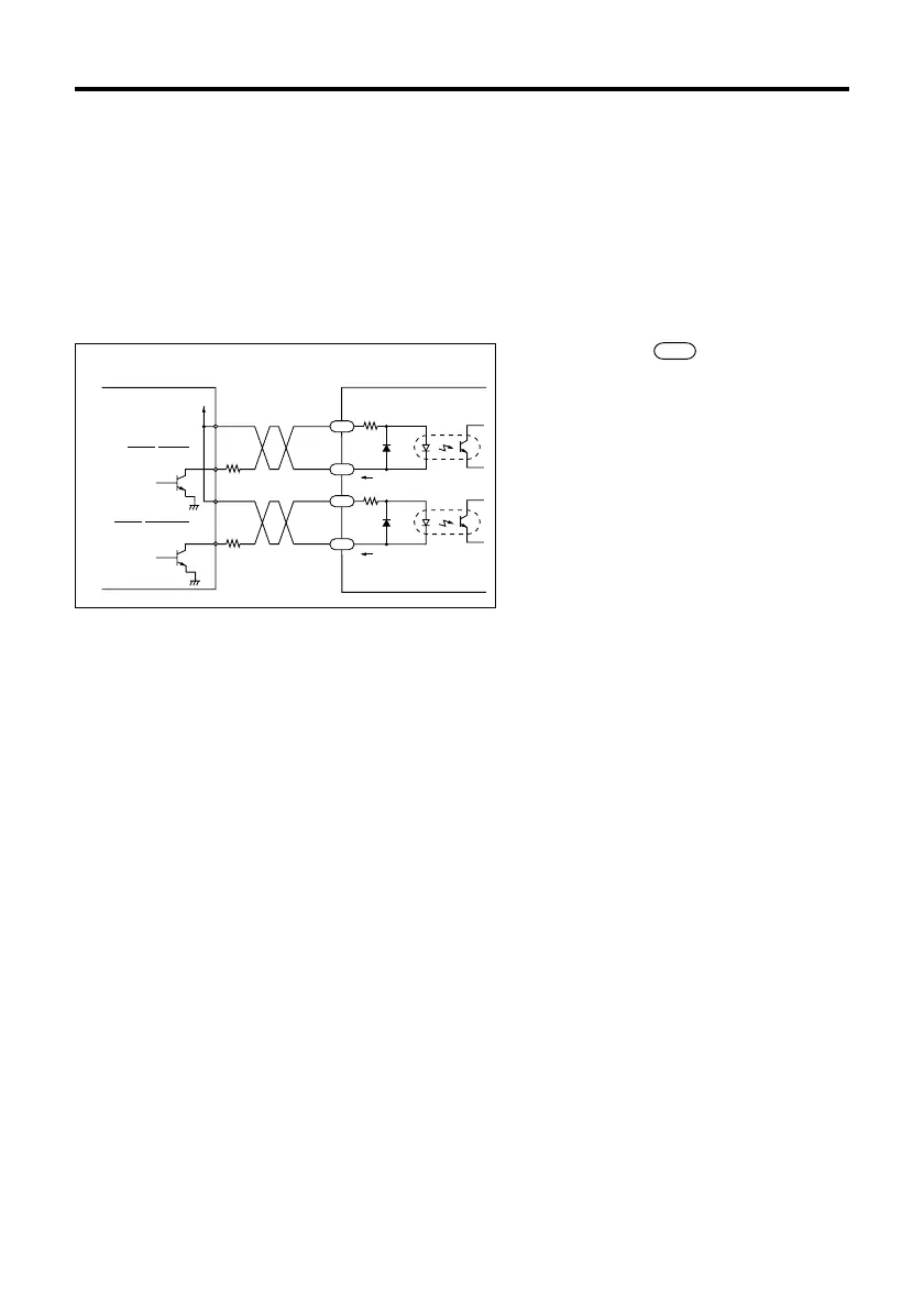
V
0
R
R
Pulse(CW)
Rotation direction(CCW)
220Ω
220Ω
20mA max.
20mA max.
Controller output
Driver input
(Internal circuit)
Open collector
output
CW/P.
CCW/D.
PLS(CW)
DIR.(CCW)
+
+
‑
‑
2
1
3
4
The number within refers to the pin
number of driver connector SIGNAL 1.
The information in the brackets ( ) refers to
signals when in 2-pulse input mode.
Keep the voltage between DC5V and DC24V.
When voltage is equal to DC5V, external
resistance R is not necessary.
When voltage is above DC5V, connect
external resistance R and keep the input
current below 20mA.
Input/output signals
Input signals
The input signals to the driver and their functions are specified below.
Pulse/CW pulse signals
Rotation direction/CCW pulse signals
The diagram below shows the input circuits and an example connection to a controller.