18
All windings off signal
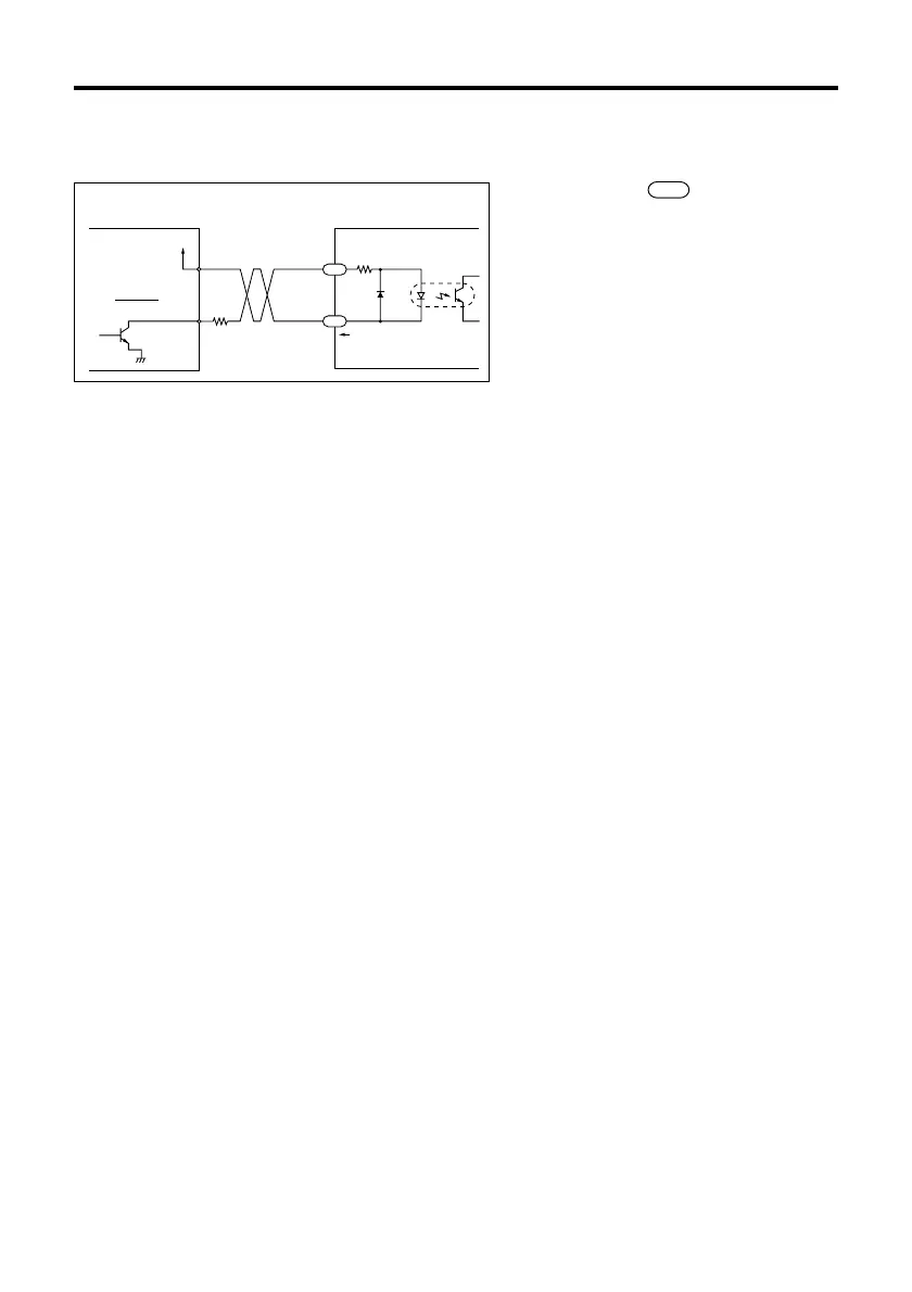
The diagram below shows the input circuit and an example connection to a controller.
The number within refers to the pin
number of driver connector SIGNAL 1.
Keep the voltage between DC5V and DC24V.
When voltage is equal to DC5V, external
resistance R is not necessary.
When voltage is above DC5V, connect
external resistance R, and keep the input
current below 20mA.
R
+
220Ω
20mA max.
Controller output
Open collector
output
‑
Driver input
(Internal circuit)
C.OFF
C.OFF
5
6
V
0
When the all windings off signal is in the “photocoupler ON” state, the current to the motor
is cut off and motor torque is reduced to zero. The motor output shaft can then be rotated
freely by hand.
When the all windings off signal is in the “photocoupler OFF” state, the motor holding
torque is proportional to the current set by the current adjustment rotary switches. During
motor operation be sure to keep the signal in the “photocoupler OFF” state.
This signal is used when moving the motor by external force or manual home positioning
etc. is desired. If this function is not needed, it is not necessary to connect this terminal.
Switching the all windings off signal from “photocoupler ON” to “photocoupler OFF” does
not alter the excitation sequence.
When the motor shaft is manually adjusted with the all windings off signal input, the shaft
will shift up to ±3.6°
(geared type: ±3.6°/gear ratio) from the position set after the all windings off signal is
released.